Mercedes-Benz Sprinter / Dodge Sprinter. Manual - part 473


  Index      Mercedes     Mercedes-Benz Sprinter / Dodge Sprinter - service repair manual 2006 year


Search            


Content   ..  471  472  473  474   ..


Mercedes-Benz Sprinter / Dodge Sprinter. Manual - part 473


marked permanently on the inside of the rim in the
tire well. This permanent mark may be a paint dot
or line, a permanent label or a stamped impression
such as an X. An optional location mark is a small
spherical indentation on the vertical face of the out-
board flange on some non styled base steel wheels.
The tire must be removed to locate the permanent
mark on the inside of the wheel.

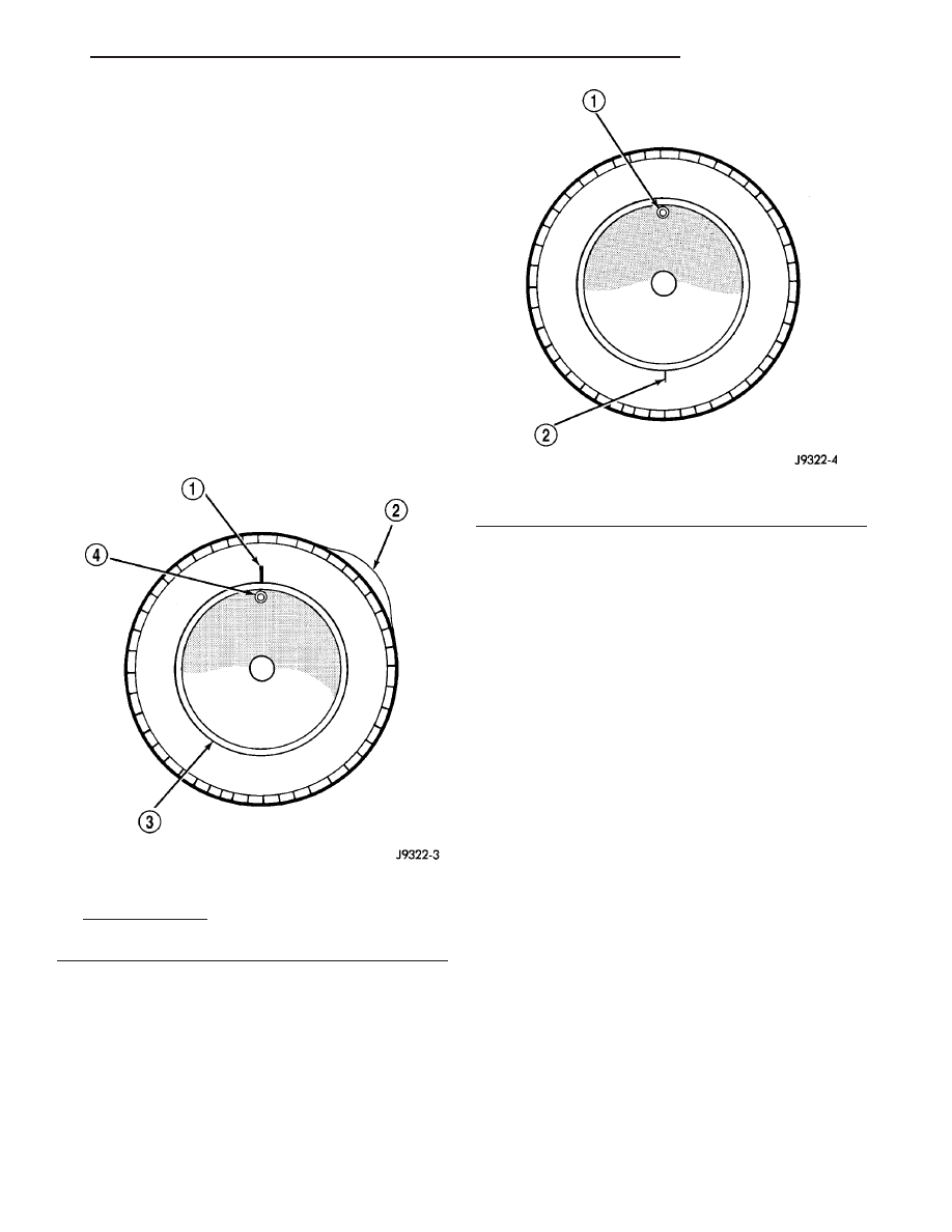
Before dismounting a tire from its wheel, a refer-

ence mark should be placed on the tire at the valve
stem location. This reference will ensure that it is
remounted in the original position on the wheel.

(1) Remove the tire and wheel assembly from the

vehicle and mount on a service dynamic balance
machine.

(2) Measure the total runout on the center of the

tire tread rib with a dial indicator. Record the indi-
cator reading. Mark the tire to indicate the high spot.
Place a mark on the tire at the valve stem location
(Fig. 4).

(3)

Break down the tire and remount it 180

degrees on the rim (Fig. 5).

(4) Measure the total indicator runout again. Mark

the tire to indicate the high spot.

(5) If runout is still excessive, the following proce-

dures must be done.

• If the high spot is within 101.6 mm (4.0 in.) of

the first spot and is still excessive, replace the tire.

• If the high spot is within 101.6 mm (4.0 in.) of

the first spot on the wheel, the wheel may be out of
specifications. Refer to Wheel and Tire Runout.

• If the high spot is NOT within 101.6 mm (4.0

in.) of either high spot, draw an arrow on the tread
from second high spot to first. Break down the tire
and remount it 90 degrees on rim in that direction
(Fig. 6). This procedure will normally reduce the
runout to an acceptable amount, if not replace the
rim.

Fig. 4 First Measurement On Tire

1 - REFERENCE MARK
2 - 1ST MEASUREMENT
HIGH SPOT MARK TIRE AND RIM
3 - WHEEL
4 - VALVE STEM

Fig. 5 Remount Tire 180 Degrees

1 - VALVE STEM
2 - REFERENCE MARK

VA

TIRES/WHEELS

22 - 3

STANDARD PROCEDURE - TIRE AND WHEEL
BALANCE

It is recommended that a two plane service

dynamic balancer be used when a tire and wheel
assembly require balancing. Refer to balancer opera-
tion instructions for proper cone mounting proce-
dures. Typically use front cone mounting method for
steel wheels. For aluminum wheel use back cone
mounting method without cone spring.

NOTE: Static should be used only when a two plane
balancer is not available.

NOTE: Cast aluminum and forged aluminum wheels
require coated balance weights and special align-
ment equipment.

Wheel balancing can be accomplished with either

on or off vehicle equipment. When using on-vehicle
balancing equipment, remove the opposite wheel/tire.
Off-vehicle balancing is recommended.

For static balancing, find the location of the heavy

spot causing the imbalance. Counter balance wheel
directly opposite the heavy spot. Determine weight
required to counter balance the area of imbalance.
Place half of this weight on the inner rim flange and
the other half on the outer rim flange (Fig. 7).

For dynamic balancing, the balancing equipment is

designed to locate the amount of weight to be applied
to both the inner and outer rim flange (Fig. 8).

Fig. 6 Remount Tire 90 Degrees In Direction of

Arrow

1 - 2ND HIGH SPOT ON TIRE
2 - 1ST HIGH SPOT ON TIRE

22 - 4

TIRES/WHEELS

VA

Fig. 7 Static Unbalance & Balance

1 - HEAVY SPOT
2 - CENTER LINE OF SPINDLE
3 - ADD BALANCE WEIGHTS HERE

4 - CORRECTIVE WEIGHT LOCATION
5 - TIRE OR WHEEL TRAMP, OR WHEEL HOP

VA

TIRES/WHEELS

22 - 5

STANDARD PROCEDURE - TIRE ROTATION

Tires on the front and rear axles operate at differ-

ent loads and perform different steering, driving, and
braking functions. For these reasons, the tires wear
at unequal rates. They may also develop irregular
wear patterns. These effects can be reduced by rotat-
ing the tires according to the maintenance schedule
in the Owners Manual. This will improve tread life,
traction and maintain a smooth quiet ride.

The recommended method of tire rotation is (Fig.

9) & (Fig. 10). Other methods can be used, but may
not provide the same tire longevity benefits.

CAUTION: 3500 Dual rear tires have a new tire rota-
tion pattern. This is to accommodate the asymmet-
rical design of the ON/OFF road tires and the use of
the outlined white letter (OWL) tires. When replac-
ing a flat, the spare tire may have to be remounted
on the rim or installed at a different location to
maintain the correct placement of the asymmetrical
design or the (OWL).

Fig. 8 Dynamic Unbalance & Balance

1 - CENTER LINE OF SPINDLE
2 - ADD BALANCE WEIGHTS HERE

3 - CORRECTIVE WEIGHT LOCATION
4 - HEAVY SPOT WHEEL SHIMMY AND VIBRATION

Fig. 9 TIRE ROTATION PATTERN - SINGLE REAR

WHEEL (SRW)

Fig. 10 TIRE ROTATION PATTERN - DUAL REAR

WHEELS (DRW)

22 - 6

TIRES/WHEELS

VA


Content   ..  471  472  473  474   ..