Mercedes-Benz Sprinter / Dodge Sprinter. Manual - part 455


  Index      Mercedes     Mercedes-Benz Sprinter / Dodge Sprinter - service repair manual 2006 year


Search            


Content   ..  453  454  455  456   ..


Mercedes-Benz Sprinter / Dodge Sprinter. Manual - part 455


Overlap Regulating Valve

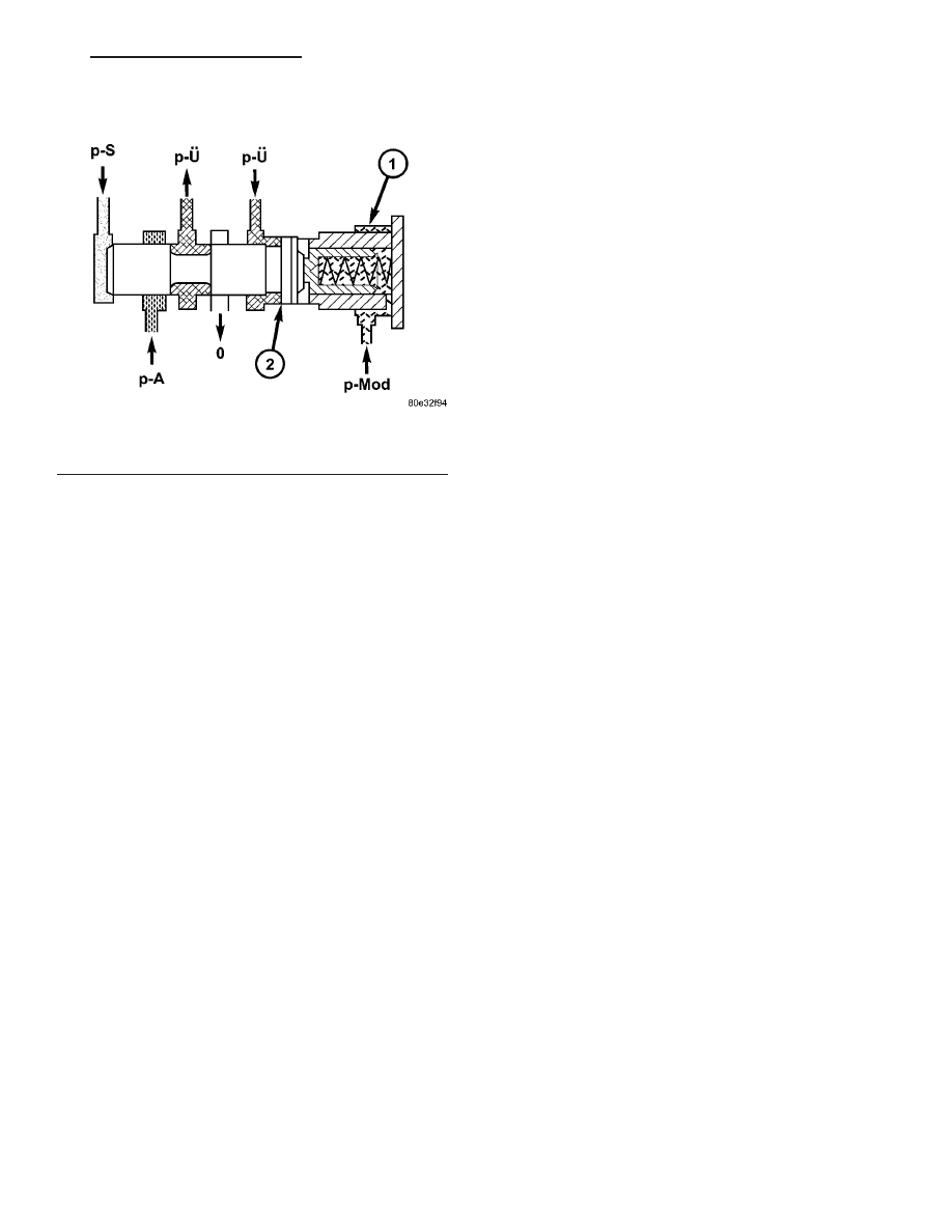
During the shift phase the pressure (Fig. 114) in

the deactivating shift actuator is regulated in rela-
tion to the engine load (modulating pressure, p-Mod)
and the pressure in the activating actuator. The reg-
ulated pressure is inversely proportional to the trans-
fer capacity of the activating shift actuator (regulated
overlap).

Fig. 114 Overlap Regulating Valve

1 - OVERLAP REGULATING VALVE
2 - ANNULAR SURFACE ON OVERLAP REGULATING VALVE

VA

AUTOMATIC TRANSMISSION NAG1 - SERVICE INFORMATION

21 - 115

Command Valve

When the end face is unpressurized (stationary

phase), the working pressure (p-A) is directed to the
actuated shift element. If the end face of the com-
mand valve (Fig. 115) is subjected to the shift valve
pressure (p-SV) (shift phase), then the shift pressure
(p-S) is switched to the activating element and the
overlap pressure (p-Ü) is switched to the deactivating
element.

Fig. 115 Command Valve

1 - HOLDING CLUTCH B1
2 - DRIVING CLUTCH K1

3 - 1-2/4-5 COMMAND VALVE

21 - 116

AUTOMATIC TRANSMISSION NAG1 - SERVICE INFORMATION

VA

Shift Valve Holding Pressure

The holding pressure shift valve (1) (Fig. 116) is

actuated by the pressures present at the end face in
the actuators and a spring. It assigns the working
pressure (p-A) to the actuator with the higher pres-
sure (taking into account the spring force and the
effective surface area). The other element of the shift
group is then unpressurized. The valve switches over
only during the shift phase and only at a certain
pressure ratio between the overlap pressure (p-Ü)
and the shift pressure (p-S).

Fig. 116 Shift Valve Holding Pressure

1 - HOLDING PRESSURE SHIFT VALVE

VA

AUTOMATIC TRANSMISSION NAG1 - SERVICE INFORMATION

21 - 117

Shift Pressure Shift Valve

When the multiple-disc brake B1 (3) is activated,

the working pressure (p-A) is applied to the end face
of the 1-2 / 4-5 shift pressure shift valve (4) (Fig. 117)
via the command valve (1). Its shift state is main-
tained during the shift phase by substituting the
shift element pressure acting on its end face (and
which is variable during the shift phase) with a cor-
responding constant pressure. When the multi-plate
clutch K1 (2) is activated, the end face of the shift
valve is unpressurized during the stationary and
shift phases, so the shift state is maintained during
the shift phase in this case too.

Lubrication Pressure Regulating Valve

At the working pressure regulating valve surplus

oil is diverted to the lubrication pressure regulating
valve (1) (Fig. 118), from where the lubrication pres-
sure (p-Sm) is used in regulated amounts to supply
the transmission lubrication system including the
torque converter.

Fig. 117 Shift Pressure Shift Valve

1 - 1-2/4-5 COMMAND VALVE
2 - DRIVING CLUTCH K1

3 - HOLDING CLUTCH B1
4 - 1-2/4-5 SHIFT PRESSURE SHIFT VALVE

Fig. 118 Lubrication Pressure Regulating Valve

1 - LUBRICATION PRESSURE REGULATING VALVE

21 - 118

AUTOMATIC TRANSMISSION NAG1 - SERVICE INFORMATION

VA


Content   ..  453  454  455  456   ..