Mercedes-Benz Sprinter / Dodge Sprinter. Manual - part 398
 

  Index      Mercedes     Mercedes-Benz Sprinter / Dodge Sprinter - service repair manual 2006 year


Search            


Content   ..  396  397  398  399   ..


Mercedes-Benz Sprinter / Dodge Sprinter. Manual - part 398


REMOVAL

(1) Disconnect negative battery cable.
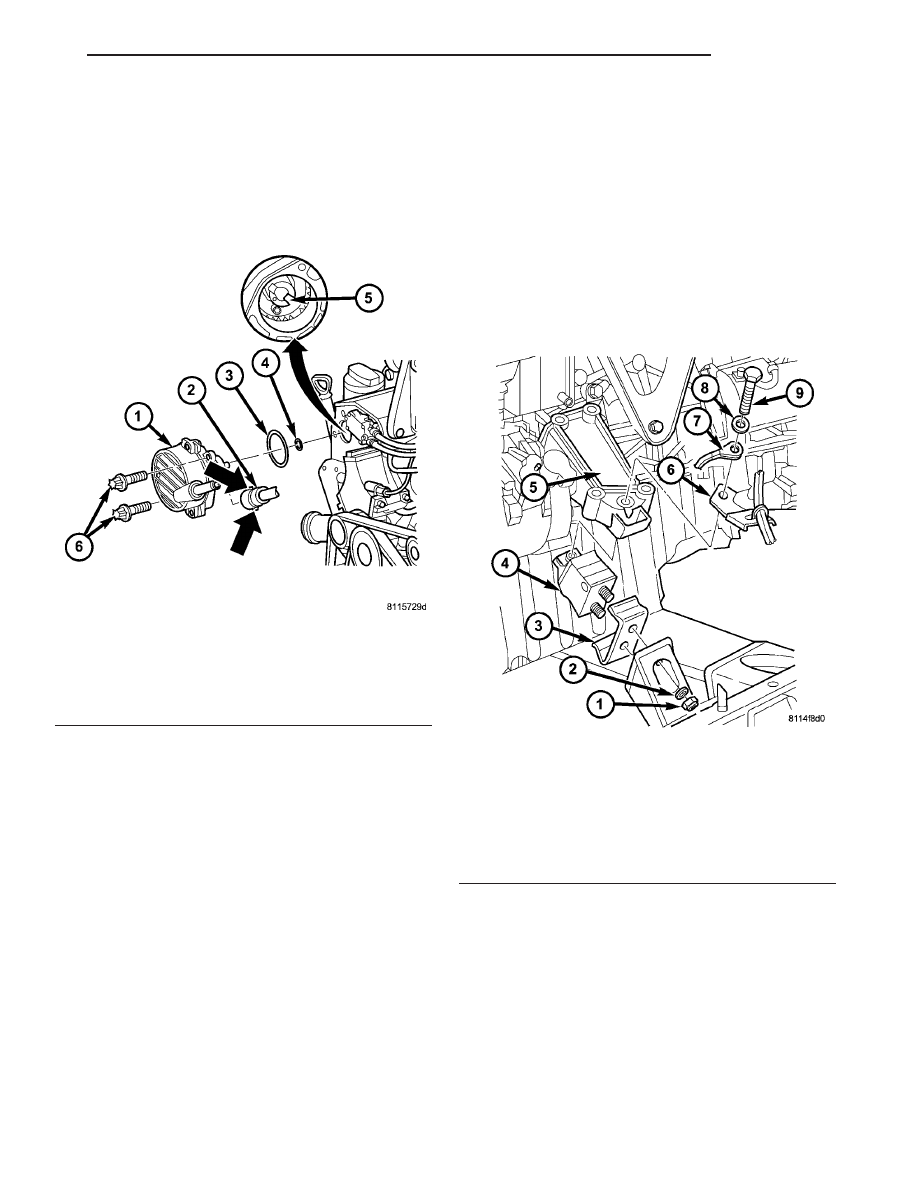
(2) Remove vacuum line at vacuum pump (Fig.

48).

NOTE: Observe position of driver on rear of pump.

(3) Remove vacuum pump and seals (Fig. 48)

(4) Clean all sealing surfaces.

INSTALLATION

(1) Clean all sealing surfaces.
(2) Position driver on rear of pump and install vac-

uum pump with new seals. Tighten bolts to 14N·m
(124 lbs. in.). (Fig. 48)

(3) Install vacuum line to vacuum pump (Fig. 48).
(4) Connect negative battery cable.

WARNING: USE EXTREME CAUTION WHEN THE
ENGINE IS OPERATING. DO NOT STAND IN A
DIRECT LINE WITH THE FAN. DO NOT PUT YOUR
HANDS NEAR THE PULLEYS, BELTS OR FAN. DO
NOT WEAR LOOSE CLOTHES.

(5) Start the engine and inspect for leaks.

LEFT MOUNT

REMOVAL

(1) Install engine support fixture #8534 with adap-

tors #8534–16 and raise the engine slightly.

(2) Raise and support the vehicle.
(3) Remove the engine mount bolts (Fig. 49)
(4) Lower the vehicle.
(5) Using the engine support fixture # 8934, raise

the engine until the weight is no longer on the
mounts.

(6) Raise and support the vehicle.
(7) Remove the engine mount nuts and remove the

mount (Fig. 49)

INSTALLATION

(1) Position the engine mount into the stop plate

(Fig. 49)

(2) Position the engine mount into position and

tighten the retaining nuts to 45 N·m (33 lbs. ft.) (Fig.
49)

(3) Lower the vehicle.
(4) Lower the engine on to the engine mounts until

they contact (Fig. 49)

(5) Hand tighten the engine support to engine

mount bolt (Fig. 49).

Fig. 48 VACUUM PUMP

1 - VACUUM PUMP
2 - VACUUM LINE
3 - O-RING
4 - O-RING
5 - EXHAUST CAMSHAFT
6 - BOLTS

Fig. 49 LEFT ENGINE MOUNT

1 - NUT
2 - WASHER
3 - STOP PLATE
4 - ENGINE MOUNT
5 - ENGINE SUPPORT
6 - BRACKET
7 - GROUND CABLE
8 - WASHER
9 - BOLT

VA

ENGINE

9 - 55

(6) Lower the engine on to the engine mount and

tighten bolt to 83 N·m (61 lbs.ft.) (Fig. 49)

(7) Remove the engine support fixture and adap-

tors.

RIGHT MOUNT

REMOVAL

(1) Install engine support fixture #8534 with adap-

tors #8534-16 and raise the engine slightly.

(2) Raise and support the vehicle.
(3) Remove the engine mount bolts (Fig. 50)
(4) Lower the vehicle.
(5) Using the engine support fixture, raise the

engine until the weight is no longer on the mounts.

(6) Raise and support the vehicle.
(7) Remove the engine mount nuts and remove the

mount (Fig. 50)

INSTALLATION

(1) Position the engine mount into the stop plate

(Fig. 50)

(2) Position the engine mount into position and

tighten the retaining nuts to 45 N·m (33 lbs. ft.) (Fig.
50)

(3) Lower the vehicle.
(4) Lower the engine on to the engine mounts until

they contact (Fig. 50)

(5) Hand tighten the engine support to engine

mount bolt (Fig. 50).

(6) Lower the engine on to the engine mount and

tighten bolt to 83 N·m (61 lbs.ft.) (Fig. 50)

(7) Remove the engine support fixture and adap-

tors.

OIL

REMOVAL - OIL SEPARATOR

(1) Disconnect breather hose.
(2) Remove the separator retaining bolts
(3) Twist to remove oil separator from cover.

INSTALLATION - OIL SEPARATOR

(1) Lubricate the oil separator o - ring with clean

engine oil.

(2) Position separator above cover and apply down-

ward pressure to seat.

(3) Install retaining bolts and tighten to 8N·m (70

lbs. in.).

(4) Connect breather hose.

OIL COOLER & LINES

REMOVAL

WARNING: RISK OF INJURY TO SKIN AND EYES
DUE TO SCALDING FROM HOT COOLANT. DO NOT
OPEN THE COOLING SYSTEM UNLESS THE TEM-
PERATURE IS BELOW 194°F (90°C). WEAR PRO-
TECTIVE CLOTHING AND EYE WEAR. RISK OF
POISONING IF COOLANT IS SWALLOWED. STORE
COOLANT

IN

PROPER

AND

APPROPRIATELY

MARKED CONTAINERS.

(1) Partailly drain cooling system.
(2) Remove the oil filter.
(3) Remove the coolant hoses from the oil cooler

(Fig. 51).

(4) Remove the oil cooler from the timing case

cover (Fig. 51).

Fig. 50 RIGHT ENGINE MOUNT

1 - NUT
2 - WASHER
3 - STOP PLATE
4 - ENGINE MOUNT
5 - ENGINE SUPPORT
6 - WASHER
7 - BOLT

9 - 56

ENGINE

VA

INSTALLATION

(1) Clean all sealing surfaces.
(2) Install the engine oil cooler to the timing case

cover with a new gasket. Tighten bolts to 14N·m (124
lbs. in.) (Fig. 51).

(3) Reconnect

the

coolant

hoses

and

tighten

clamps.

(4) Install new oil filter and tighten oil filter cap to

25N·m ( 18 lbs. ft.) (Fig. 51).

(5) Refill cooling system.
(6) Start engine and inspect for leaks.
(7) Turn engine off and check engine oil level. Add

as necessary.

OIL FILTER

REMOVAL

(1) Unscrew the oil filter cap (Fig. 52)
(2) Remove clean and inspect cap gasket, replace

as necessary.

(3) Remove oil filter (Fig. 52).

INSTALLATION

(1) Inspect oil filter cap gasket, if all right, lubri-

cate with clean engine oil.

(2) Install oil filter.
(3) Screw oil filter cap to housing and tighten to

25N·m (18 lbs. ft.) (Fig. 52). Adjust oil level as neces-
sary.

OIL JET

DESCRIPTION

There are five oil jets installed in the engine block

(Fig. 53). These oil jets are used to cool and lubricate
the piston assemblies.

Fig. 51 ENGINE OIL COOLER

1 - OIL FILTER
2 - OIL FILTER COVER
3 - GASKET
4 - BOLT
5 - COOLANT HOSE
6 - ENGINE OIL COOLER

Fig. 52 ENGINE OIL COOLER

1 - OIL FILTER
2 - OIL FILTER COVER
3 - GASKET
4 - BOLT
5 - COOLANT HOSE
6 - ENGINE OIL COOLER

VA

ENGINE

9 - 57

REMOVAL

The engine must be removed from the vehicle and

completely dissassembled to replace the oil jets.

(1) Remove engine from vehicle.
(2) Completely dissassemble engine.
(3) Using an extraction claw #9746 (3) and a slide

hammer (1), remove the oil jets (2) from engine block
(Fig. 54).

INSTALLATION

(1) Install oil jet into special tool #8924.
(2) Align oil jet in location in engine block.

NOTE: Align oil jet with the groove in special tool
#8924.

(3) Drive oil jets into block using special tool #8924

until oil jet is fully seated into engine block (Fig.
55).

(4) Reassemble engine.
(5) Install engine into vehicle.

OIL PAN

REMOVAL

(1) Drain engine oil.
(2) Remove the sway bar retaining bolts and swing

sway bar down and out of the way.

(3) Remove the wiring harness duct from the oil

pan bolts and position out of the way.

(4) Lower the vehicle and remove the turbocharger

upper heat shield.

(5) Connect engine support fixture #8534 using

adaptors #8534–16, to the engine lifting eye and
raise engine slightly (Fig. 56).

Fig. 53 OIL JET LOCATION

1 - ENGINE BLOCK
2 - OIL JET

Fig. 54 OIL JET EXTRACTION CLAW

1 - SLIDE HAMMER
2 - OIL JETS
3 - EXTRACTION CLAW # 9746

Fig. 55 OIL JET INSTALLATION

1 - OIL JET INSTALLER #8942
2 - ENGINE BLOCK
3 - OIL JET

9 - 58

ENGINE

VA


Content   ..  396  397  398  399   ..