Mercedes-Benz Sprinter / Dodge Sprinter. Manual - part 259


  Index      Mercedes     Mercedes-Benz Sprinter / Dodge Sprinter - service repair manual 2006 year


Search            


Content   ..  257  258  259  260   ..


Mercedes-Benz Sprinter / Dodge Sprinter. Manual - part 259


(7) Remove the two screws that secure the wiper

linkage module motor bracket to the flange on the
underside of the cowl top panel.

(8) Remove the wiper linkage module and wiper

motor from the underside of the cowl top panel as a
unit.

(9) Remove the wiper motor from the wiper link-

age module. (Refer to 8 - ELECTRICAL/WIPERS/
WASHERS/WIPER MOTOR - REMOVAL).

INSTALLATION

(1) Reinstall the wiper motor onto the wiper link-

age module. (Refer to 8 - ELECTRICAL/WIPERS/
WASHERS/FRONT

WIPER

MOTOR

-

INSTALLATION).

(2) Carefully position the wiper linkage module

and wiper motor to the underside of the cowl top
panel as a unit (Fig. 30).

(3) Install and tighten the two screws that secure

the wiper linkage module motor bracket to the flange
on the underside of the cowl top panel. Tighten the
screws to 6 N·m (50 in. lbs.).

(4) Install and tighten the nut and washer that

secures each wiper pivot housing to the outside of the
cowl top panel.

(5) Reconnect the wiper motor pigtail wire connec-

tor to the vehicle wire harness connector.

(6) Reinstall the ventilation housing onto the dash

panel and the underside of the cowl top panel (Fig.
29).

(7) Reinstall the wiper arms onto the wiper pivots.

(Refer to 8 - ELECTRICAL/WIPERS/WASHERS/
WIPER ARM - INSTALLATION).

(8) Reconnect the battery negative cable.

WIPER MOTOR

DESCRIPTION

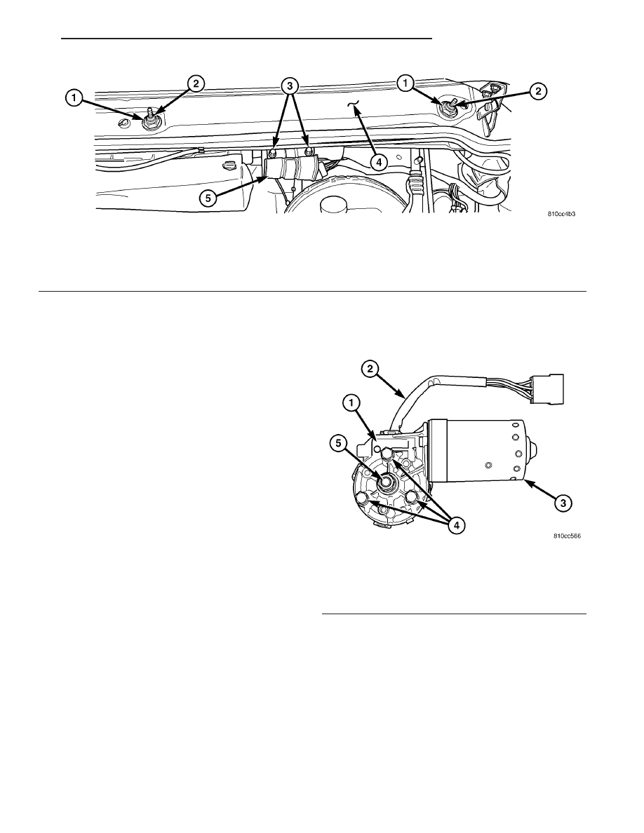
The wiper motor is secured with three screws to a

motor bracket integral to the wiper linkage module
bracket located below the cowl top panel in the
engine compartment (Fig. 31). The wiper motor out-
put shaft passes through a hole in the motor bracket,
where a nut secures the wiper motor crank arm to
the motor output shaft. The two-speed permanent
magnet wiper motor features an integral transmis-
sion, an internal park switch, and an internal Posi-
tive Temperature Coefficient (PTC) circuit breaker.

The wiper motor cannot be adjusted or repaired. If

any component of the motor is faulty or damaged, the
entire wiper motor unit must be replaced.

Fig. 30 Wiper Linkage Module Remove/Install

1 - NUT & WASHER (2)

4 - COWL TOP PANEL

2 - PIVOT (2)

5 - MOTOR BRACKET

3 - SCREW (2)

Fig. 31 Wiper Motor

1 - TRANSMISSION
2 - PIGTAIL WIRE
3 - MOTOR
4 - SCREW (3)
5 - OUTPUT SHAFT

VA

WIPERS/WASHERS

8R - 31

OPERATION

The wiper motor operation is controlled by the

vehicle operator through battery current inputs
received by the wiper motor from the wiper switch
circuitry of the multi-function switch on the top of
the steering column, and from the wiper relay on the
fuse block underneath the steering column. The
wiper motor speed is controlled by current flow to
either the low speed or the high speed set of brushes.
The automatic resetting circuit breaker protects the
motor from overloads.

The park switch consists of a contact disc and

three contacts. The contact disc is mechanically fas-
tened to and rotated with a gear in the wiper motor
transmission. Two input contacts alternately close
the wiper park switch sense output circuit contact to
ground or to battery current, depending upon the
position of the wipers on the glass. This feature
allows the intermittent wipe logic circuit to monitor
the position and the cycles of the wiper motor to pro-
vide the intermittent wipe and wipe-after-wash
modes, as well as allowing the motor to complete its
current wipe cycle after the wiper system has been
turned Off and park the wiper blades in the lowest
portion of the wipe pattern.

The wiper motor may be diagnosed using conven-

tional diagnostic tools and methods.

REMOVAL

(1) Disconnect and isolate the battery negative

cable.

(2) Disconnect the vehicle wire harness connector

for the wiper motor from the motor pigtail wire con-
nector (Fig. 32).

8R - 32

WIPERS/WASHERS

VA

(3) Remove the nut that secures the motor crank

arm to the wiper motor output shaft.

(4) If this wiper motor is to be reinstalled, make

an index mark between the wiper motor output shaft
and the motor crank arm using a suitable marker.

(5) Disengage the motor crank arm from the wiper

motor output shaft.

(6) Remove the three screws that secure the wiper

motor to the wiper linkage module motor bracket.

(7) Remove the wiper motor from the wiper link-

age module motor bracket.

INSTALLATION

(1) Position the wiper motor to the underside of

the wiper linkage module motor bracket (Fig. 32).

(2) Install and tighten the three screws that secure

the wiper motor to the wiper linkage module motor
bracket. Tighten the screws to 12 N·m (105 in. lbs.).

(3) If this wiper motor is being reinstalled, position

the motor crank arm on the wiper motor output shaft
so that the index marks made during the removal
procedure are aligned. If this is a new wiper motor
installation, the motor crank arm should be installed

so that it is pointed toward the left (driver) side of
the vehicle and parallel with the two wiper drive
links while both wiper blades are positioned on their
alignment marks near the lower edge of the wind-
shield glass.

(4) Install and tighten the nut that secures the

motor crank arm to the wiper motor output shaft.
Tighten the nut to 12 N·m (105 in. lbs.).

(5) Reconnect the vehicle wire harness connector

for the wiper motor to the motor pigtail wire connec-
tor.

(6) Reconnect the battery negative cable.

Fig. 32 Wiper Motor Remove/Install

1 - NUT

4 - PIGTAIL WIRE CONNECTOR

2 - LINK (2)

5 - WIPER MOTOR

3 - MOTOR CRANK ARM

6 - SCREW (3)

VA

WIPERS/WASHERS

8R - 33

WIPER RELAY

DESCRIPTION

A wiper relay is standard equipment on all models.

The wiper relay (or intermittent wipe relay) is
located in a dedicated receptacle on the bottom left of
the fuse block on the underside of the steering col-
umn (Fig. 33). The wiper relay is a conventional
International Standards Organization (ISO) micro
relay. Relays conforming to the ISO specifications
have common physical dimensions, current capaci-
ties, terminal patterns, and terminal functions. The
relay is contained within a small, rectangular,
molded plastic housing. The relay is connected to all
of the required inputs and outputs through the
instrument panel wire harness connector by five
male spade-type terminals that extend from the bot-
tom of the relay base. The ISO designation for each
terminal is molded into the base adjacent to the ter-
minal. The ISO terminal designations are as follows:

• 30 (Common Feed) - This terminal is con-

nected to the movable contact point of the relay.

• 85 (Coil Ground) - This terminal is connected

to the ground feed side of the relay control coil.

• 86 (Coil Battery) - This terminal is connected

to the battery feed side of the relay control coil.

• 87 (Normally Open) - This terminal is con-

nected to the normally open fixed contact point of the
relay.

• 87A (Normally Closed) - This terminal is con-

nected to the normally closed fixed contact point of
the relay.

The wiper relay cannot be adjusted or repaired. If

the relay is damaged or faulty, it must be replaced.

OPERATION

The wiper relay (or intermittent wipe relay) is an

electromechanical switch that uses a low current
input from the intermittent wipe logic circuitry
within the fuse block underneath the steering column
to control a high current output to the low speed
brush of the wiper motor. The movable common feed
contact point is held against the fixed normally
closed contact point by spring pressure. When the
relay coil is energized, an electromagnetic field is
produced by the coil windings. This electromagnetic
field draws the movable relay contact point away
from the fixed normally closed contact point, and
holds it against the fixed normally open contact
point. When the relay coil is de-energized, spring
pressure returns the movable contact point back
against the fixed normally closed contact point. A
resistor or diode is connected in parallel with the
relay coil in the relay, and helps to dissipate voltage
spikes and electromagnetic interference that can be
generated as the electromagnetic field of the relay
coil collapses.

The wiper relay terminals are connected to the

vehicle electrical system through a connector recepta-
cle in the fuse block. The inputs and outputs of the
wiper relay include:

• The common feed terminal (30) provides an out-

put to the wiper motor low speed brush through the
wiper control circuitry of the multi-function switch on
the steering column. When the wiper relay is de-en-
ergized, the common feed terminal is connected to
the input of the relay normally closed terminal (87).
When the wiper relay is energized, the common feed
terminal is connected to the input of the relay nor-
mally open terminal (87A).

• The coil ground terminal (85) is connected to

battery current through a fused ignition switch out-
put circuit whenever the ignition switch is in the On
position.

• The coil battery terminal (86) is connected to the

relay control output of the wiper, turn signals and
engine start control module within the fuse block
through the wiper relay control circuit. This elec-
tronic circuitry controls the ground path for this cir-
cuit internally to energize or de-energize the wiper
relay control coil based upon its programming and
inputs from the wiper and washer control circuitry of
the multi-function switch, the wiper motor park
switch, and the ignition switch.

• The normally open terminal (87) is connected to

the output of the wiper motor park switch through
the wiper motor park switch sense circuit. This cir-
cuit can carry either battery current (wipers are not
in park position) or ground (wipers are in park posi-
tion), depending upon the status of the wiper park
switch.

Fig. 33 Wiper Relay

1 - HOUSING
2 - TERMINAL (5)
3 - BASE

8R - 34

WIPERS/WASHERS

VA


Content   ..  257  258  259  260   ..