Mercedes-Benz Sprinter / Dodge Sprinter. Manual - part 233


  Index      Mercedes     Mercedes-Benz Sprinter / Dodge Sprinter - service repair manual 2006 year


Search            


Content   ..  231  232  233  234   ..


Mercedes-Benz Sprinter / Dodge Sprinter. Manual - part 233


MULTI - FUNCTION SWITCH

REMOVAL

WARNING: To avoid personal injury or death, on
vehicles equipped with airbags, disable the supple-
mental

restraint

system

before

attempting

any

steering wheel, steering column, airbag, seat belt
tensioner, or instrument panel component diagno-
sis or service. Disconnect and isolate the battery
negative (ground) cable, then wait two minutes for
the system capacitor to discharge before perform-
ing further diagnosis or service. This is the only
sure way to disable the supplemental restraint sys-
tem. Failure to take the proper precautions could
result in accidental airbag deployment.

(1) Disconnect and isolate the battery negative

cable.

(2) Remove the fuse block from the underside of

the steering column. (Refer to 8 - ELECTRICAL/
POWER

DISTRIBUTION/FUSE

BLOCK

-

REMOVAL).

(3) Remove the clockspring from the steering col-

umn. (Refer to 8 - ELECTRICAL/RESTRAINTS/
CLOCKSPRING - REMOVAL).

(4) If the vehicle is so equipped, remove the steer-

ing angle sensor from the steering column. (Refer to
5

-

BRAKES/ELECTRICAL/STEERING

ANGLE

SENSOR - REMOVAL).

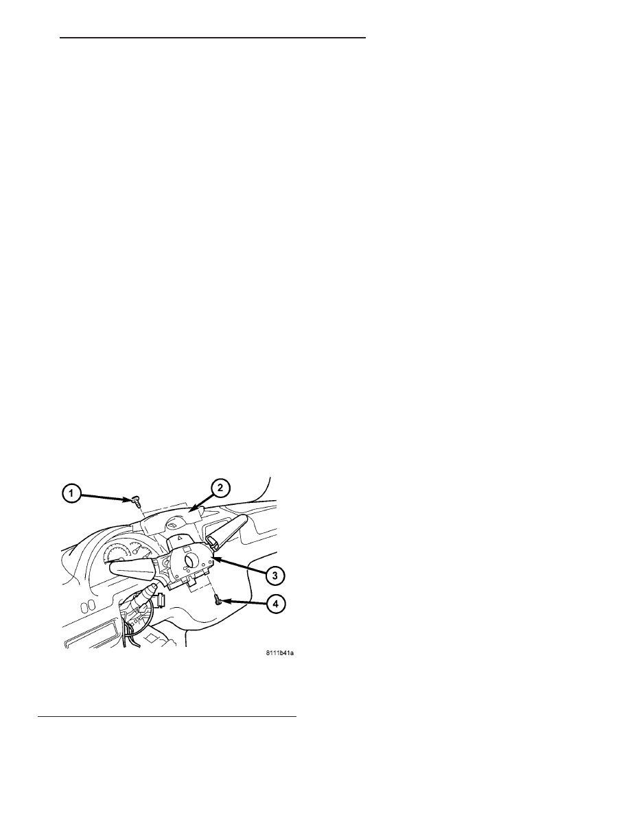
(5) Remove the two screws that secure the upper

shroud to the top of the multi-function switch (Fig.
37).

(6) Remove the upper shroud from the top of the

multi-function switch.

(7) Remove the two screws that secure the multi-

function switch to the steering column.

(8) Remove the multi-function switch from the

steering column.

(9) Remove the speed control switch from the back

of the multi-function switch. (Refer to 8 - ELECTRI-
CAL/SPEED CONTROL/SWITCH - REMOVAL).

INSTALLATION

WARNING: To avoid personal injury or death, on
vehicles equipped with airbags, disable the supple-
mental

restraint

system

before

attempting

any

steering wheel, steering column, airbag, seat belt
tensioner, or instrument panel component diagno-
sis or service. Disconnect and isolate the battery
negative (ground) cable, then wait two minutes for
the system capacitor to discharge before perform-
ing further diagnosis or service. This is the only
sure way to disable the supplemental restraint sys-
tem. Failure to take the proper precautions could
result in accidental airbag deployment.

(1) Reinstall the speed control switch onto the

back of the multi-function switch. (Refer to 8 - ELEC-
TRICAL/SPEED CONTROL/SWITCH - INSTALLA-
TION).

(2) Position the multi-function switch onto the

steering column (Fig. 37).

(3) Install and tighten the two screws that secure

the multi-function switch to the steering column.

(4) Position the upper shroud onto the top of the

multi-function switch.

(5) Install and tighten the two screws that secure

the upper shroud to the top of the multi-function
switch.

(6) If the vehicle is so equipped, reinstall the steer-

ing angle sensor onto the steering column. (Refer to 5
- BRAKES/ELECTRICAL/STEERING ANGLE SEN-
SOR - INSTALLATION).

(7) Reinstall the clockspring onto the steering col-

umn. (Refer to 8 - ELECTRICAL/RESTRAINTS/
CLOCKSPRING - INSTALLATION).

(8) Reinstall the fuse block onto the underside of

the steering column. (Refer to 8 - ELECTRICAL/
POWER DISTRIBUTION/FUSE BLOCK - INSTAL-
LATION).

(9) Reconnect the battery negative cable.

PARK BRAKE SWITCH

REMOVAL

(1) Remove the trim cover from the park brake

lever (Fig. 38). (Refer to 5 - BRAKES/PARKING
BRAKE/LEVER - REMOVAL).

Fig. 37 Multi-Function Switch Remove/Install

1 - SCREW (2)
2 - UPPER SHROUD
3 - SWITCH
4 - SCREW (2)

VA

LAMPS/LIGHTING - EXTERIOR

8L - 21

(2) Remove the screw that secures the park brake

switch and the ground eyelet terminal to the park
brake lever.

(3) Disengage the park brake switch from the park

brake lever.

(4) Disconnect the vehicle wire harness connector

for the park brake switch from the switch terminal.

(5) Remove the park brake switch from the park

brake lever.

INSTALLATION

(1) Position the park brake switch near the park

brake lever (Fig. 38).

(2) Reconnect the vehicle wire harness connector

for the park brake switch to the switch terminal.

(3) Engage the park brake switch into the park

brake lever.

(4) Install and tighten the screw that secures the

park brake switch and the ground eyelet terminal to
the park brake lever.

(5) Reinstall the trim cover onto the park brake

lever. (Refer to 5 - BRAKES/PARKING BRAKE/LE-
VER - INSTALLATION).

REAR SIDE MARKER LAMP
BULB

REMOVAL

(1) Disconnect and isolate the battery negative

cable.

(2) If the vehicle is so equipped, remove the trim

from the inside of the right or left rear corner pillar.

(3) From inside the vehicle, use hand pressure to

push the two latch tabs toward the center of the tail
lamp unit socket plate and pull the socket plate
straight out from the inner rear pillar (Fig. 39).

(4) Pull the socket plate away from the inner rear

pillar far enough to access the side marker lamp bulb
(Fig. 40).

(5) Remove the side marker lamp bulb from the

tail lamp socket plate.

INSTALLATION

(1) Install the side marker lamp bulb into the tail

lamp socket plate (Fig. 40).

(2) Align the socket plate with the mounting hole

in the inner rear pillar.

Fig. 38 Park Brake Switch Remove/Install

1 - LEVER
2 - SWITCH
3 - WIRE HARNESS
4 - SCREW

Fig. 39 Tail Lamp Socket Plate Remove/Install

1 - SOCKET PLATE
2 - INNER REAR PILLAR
3 - LATCH TAB (2)

Fig. 40 Tail Lamp Bulb Remove/Install

1 - BRAKE/PARK LAMP BULB
2 - BACKUP LAMP BULB
3 - TURN SIGNAL LAMP BULB
4 - SIDE MARKER LAMP BULB
5 - TAIL LAMP SOCKET PLATE

8L - 22

LAMPS/LIGHTING - EXTERIOR

VA

(3) Using hand pressure, push the socket plate

gently and evenly into the inner rear pillar mounting
hole until both latch tabs are fully engaged (Fig. 39).

(4) If the vehicle is so equipped, reinstall the trim

onto the inside of the right or left rear corner pillar.

(5) Reconnect the battery negative cable.

REAR TURN LAMP BULB

REMOVAL

(1) Disconnect and isolate the battery negative

cable.

(2) If the vehicle is so equipped, remove the trim

from the inside of the right or left rear corner pillar.

(3) From inside the vehicle, use hand pressure to

push the two latch tabs toward the center of the tail
lamp unit socket plate and pull the socket plate
straight out from the inner rear pillar (Fig. 41).

(4) Pull the socket plate away from the inner rear

pillar far enough to access the turn signal lamp bulb
(Fig. 42).

(5) Remove the turn signal lamp bulb from the tail

lamp socket plate.

INSTALLATION

(1) Install the turn signal lamp bulb into the tail

lamp socket plate (Fig. 42).

(2) Align the socket plate with the mounting hole

in the inner rear pillar.

(3) Using hand pressure, push the socket plate

gently and evenly into the inner rear pillar mounting
hole until both latch tabs are fully engaged (Fig. 41).

(4) If the vehicle is so equipped, reinstall the trim

onto the inside of the right or left rear corner pillar.

(5) Reconnect the battery negative cable.

REPEATER LAMP BULB

REMOVAL

(1) Disconnect and isolate the battery negative

cable.

(2) Remove the small or large style repeater lamp

unit from its mounting location, but do not discon-
nect it from the vehicle wire harness. (Refer to 8 -
ELECTRICAL/LAMPS/LIGHTING - EXTERIOR/RE-
PEATER LAMP - REMOVAL).

(3) Remove the bulb holder from the lens (small

type) (Fig. 43), or the lens from the lamp housing
(large type) (Fig. 44).

Fig. 41 Tail Lamp Socket Plate Remove/Install

1 - SOCKET PLATE
2 - INNER REAR PILLAR
3 - LATCH TAB (2)

Fig. 42 Tail Lamp Bulb Remove/Install

1 - BRAKE/PARK LAMP BULB
2 - BACKUP LAMP BULB
3 - TURN SIGNAL LAMP BULB
4 - SIDE MARKER LAMP BULB
5 - TAIL LAMP SOCKET PLATE

VA

LAMPS/LIGHTING - EXTERIOR

8L - 23

(4) Remove the repeater lamp bulb from the bulb

holder.

INSTALLATION

(1) Install the repeater lamp bulb into the bulb

holder (Fig. 43) or (Fig. 44).

(2) Reinstall the bulb holder into the lens (small

type), or the lens onto the lamp housing (large type).

(3) Reinstall the repeater lamp unit into its

mounting location. (Refer to 8 - ELECTRICAL/

LAMPS/LIGHTING - EXTERIOR/REPEATER LAMP
- INSTALLATION).

(4) Reconnect the battery negative cable.

REPEATER LAMP UNIT

REMOVAL

SMALL

(1) Disconnect and isolate the battery negative

cable.

(2) Using hand pressure, press the rear edge of the

repeater lamp lens/housing toward the front of the
vehicle against the spring pressure of the retaining
clip, then pull the rear edge of the lamp outward to
disengage it from the mounting hole (Fig. 45).

(3) Pull the repeater lamp housing slightly to the

rear to disengage the front edge of the unit from the
mounting hole.

(4) Disconnect the vehicle wire harness connector

from the connector receptacle of the bulb holder on
the back of the repeater lamp unit.

(5) Remove the repeater lamp unit from the vehi-

cle.

LARGE

(1) Disconnect and isolate the battery negative

cable.

(2) Remove the screw that secures the lens and

the repeater lamp housing to the fender panel (Fig.
46).

Fig. 43 Small Repeater Lamp Bulb Remove/Install

1 - LAMP HOUSING
2 - BULB HOLDER
3 - BULB

Fig. 44 Large Repeater Lamp Bulb Remove/Install

1 - LAMP HOUSING
2 - BULB
3 - LENS
4 - SCREW

Fig. 45 Small Repeater Lamp Unit Remove/Install

1 - LAMP HOUSING
2 - BULB HOLDER
3 - BULB

8L - 24

LAMPS/LIGHTING - EXTERIOR

VA


Content   ..  231  232  233  234   ..