Mercedes-Benz Sprinter / Dodge Sprinter. Manual - part 220
IGNITION CONTROL
TABLE OF CONTENTS
page
page
IGNITION CONTROL
. . . . . . . . . . . . . . . . 1
. . . . . . . . . . . . . . . . . . . . . . . . 1
GLOW PLUG
. . . . . . . . . . . . . . . . . . . . . . . . . . . . . 1
. . . . . . . . . . . . . . . . . . . . . . . . . . 1
GLOW PLUG RELAY
. . . . . . . . . . . . . . . . . . . . . . . . . . 1
. . . . . . . . . . . . . . . . . . . . . . . . . . . . 2
DIAGNOSIS AND TESTING - GLOW PLUG
. . . . . . . . . . . . . . . . . . . . . . . . . . . . . . 2
IGNITION CONTROL
OPERATION - GLOW PLUG
Pre - Glowing
With the key in the On position, the glow plug out-
put stage and the indicator lamp are actuated by the
ECM. The pre-heating time is calculated by the ECM
in line with the coolant temperature. The glow plug
output stage switches the current through the glow
plugs. The glow plug indicator lamp goes out after a
pre-glow period has elapsed. Component or cable fail-
ures in the pre-glow system are indicated by the glow
plug lamp and stored in the ECM.
Glow Output Stage
With the ignition key in the On position a signal is
transmitted from the ECM to the glow plug output
stager. If no data is exchanged with the ECM the
glow plug stage is terminated after two seconds. The
glow plug out put stage constantly signals the cur-
rent operating state (ON/OFF) and any system
faults. The following faults are recognized by the out
put stage and transmitted to the ECM:
• Open circuit in one or more of the glow plug
leads
• Short circuit in the glow plug circuit
• Out put stage fault or temperature related shut-
off
If a failure in the glow plug system occurs, the
glow plug indicator lamp will be illuminated only as
long as the fault is current. If the failure is no longer
present, the glow plug indicator lamp will be
switched off but a code will be stored in the ECM.
After Glow
Once the engine has started, the ECM determines
the after glow time depending on cooling tempera-
ture. During this time the glow plugs continue to be
actuated by the glow plug output stage. This results
in improved smooth running after a cold start and
improved warming up properties, elimination of blue
exhaust after a cold start up and a more stable cold
starting speed.
If no signal is received from the coolant tempera-
ture sensor the signal from the oil sensor is used as a
substitute.
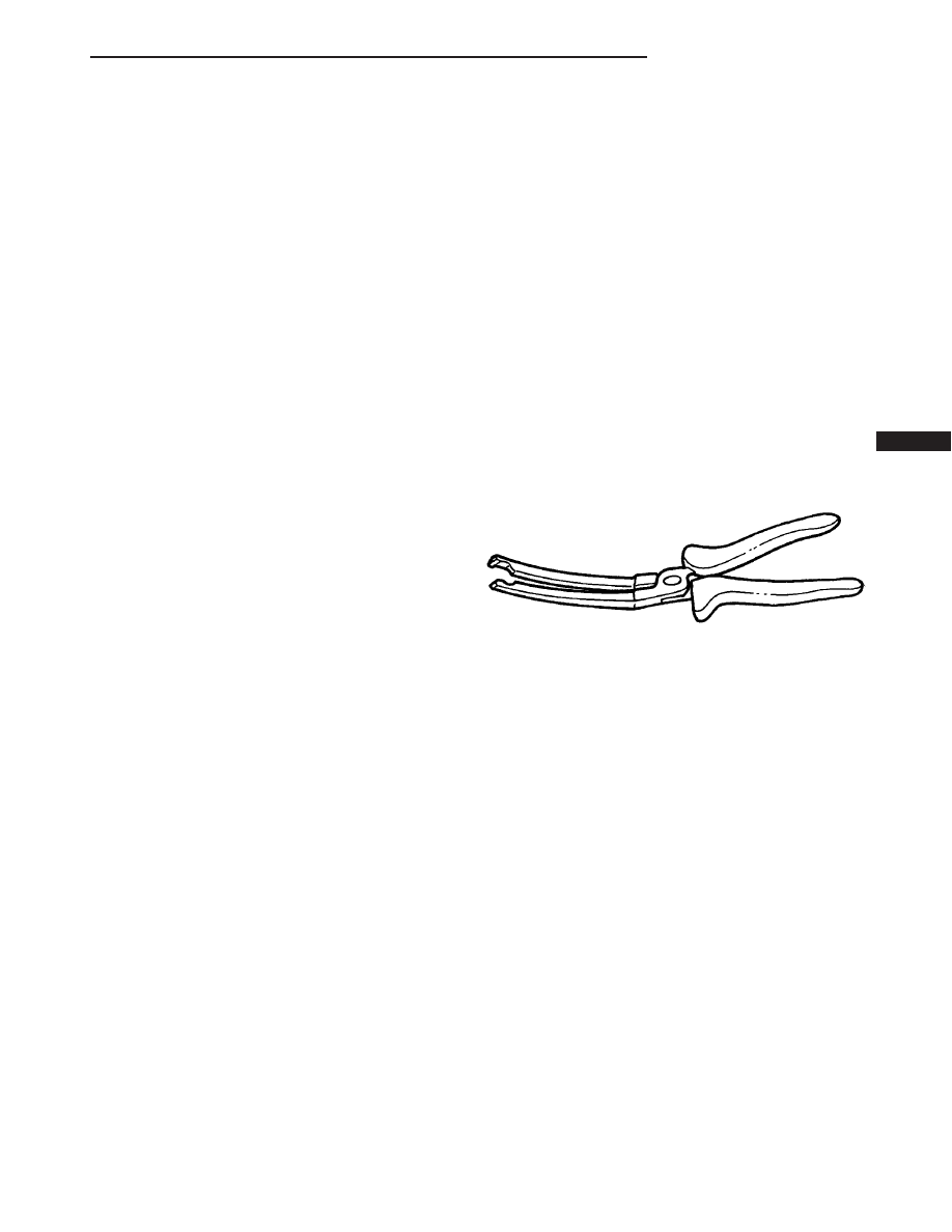
SPECIAL TOOLS
GLOW PLUG
REMOVAL
(1) Disconnect the negative battery cable.
(2) Remove the engine cover.
(3) Use special tool #9286 pliers to unplug the
glow plug wiring harness connector(s) at the glow
plug.
(4) Remove the glow plug(s) (Fig. 1).
INSTALLATION
(1) Screw glow plug(s) into cylinder head and
tighten to 12 N·m (115 lbs. in) (Fig. 1).
(2) Connect the glow plug wiring harness connec-
tor(s)
(3) Install the engine cover.
(4) Connect negative battery cable.
GLOW PLUG RELAY
DESCRIPTION
The glow plug relay supplies battery voltage to the
glow plug through a timed cycle that is related to
coolant temperature. The glow plug relay is located
under the battery. The purpose of a glow plug system
GLOW PLUG PLIERS
VA
IGNITION CONTROL
8I - 1