Mercedes-Benz Sprinter / Dodge Sprinter. Manual - part 209


  Index      Mercedes     Mercedes-Benz Sprinter / Dodge Sprinter - service repair manual 2006 year


Search            


Content   ..  207  208  209  210   ..


Mercedes-Benz Sprinter / Dodge Sprinter. Manual - part 209


(2) Disconnect and isolate the battery negative

cable. Connect the battery charger leads. Some bat-
tery chargers are equipped with polarity-sensing cir-
cuitry. This circuitry protects the battery charger and
the battery from being damaged if they are improp-
erly connected. If the battery state-of-charge is too
low for the polarity-sensing circuitry to detect, the
battery charger will not operate. This makes it
appear that the battery will not accept charging cur-
rent. See the instructions provided by the manufac-
turer of the battery charger for details on how to
bypass the polarity-sensing circuitry.

(3) Battery chargers vary in the amount of voltage

and current they provide. The amount of time
required for a battery to accept measurable charging
current at various voltages is shown in the Charge
Rate Table. If the charging current is still not mea-
surable at the end of the charging time, the battery
is faulty and must be replaced. If the charging cur-
rent is measurable during the charging time, the bat-
tery may be good and the charging should be
completed in the normal manner.

CHARGE RATE TABLE

Voltage

Hours

16.0 volts maximum

up to 4 hours

14.0 to 15.9 volts

up to 8 hours

13.9 volts or less

up to 16 hours

CHARGING TIME REQUIRED

The time required to charge a battery will vary,

depending upon the following factors:

• Battery Capacity - A completely discharged

heavy-duty battery requires twice the charging time
of a small capacity battery.

• Temperature - A longer time will be needed to

charge a battery at -18° C (0° F) than at 27° C (80°
F). When a fast battery charger is connected to a cold
battery, the current accepted by the battery will be
very low at first. As the battery warms, it will accept
a higher charging current rate (amperage).

• Charger Capacity - A battery charger that

supplies only five amperes will require a longer
charging time. A battery charger that supplies
twenty amperes or more will require a shorter charg-
ing time.

• State-Of-Charge - A completely discharged bat-

tery requires more charging time than a partially
discharged battery. Electrolyte is nearly pure water
in a completely discharged battery. At first, the
charging current (amperage) will be low. As the bat-
tery charges, the specific gravity of the electrolyte
will gradually rise.

The Battery Charging Time Table gives an indica-

tion of the time required to charge a typical battery
at room temperature based upon the battery state-of-
charge and the charger capacity.

BATTERY CHARGING TIME TABLE

Charging Amper-

age

5 Amps

10

Amps

20 Amps

Open Circuit Volt-

age

Hours Charging @ 21° C (70°

F)

12.25 to 12.49

6 hours

3 hours

1.5

hours

12.00 to 12.24

10 hours

5 hours

2.5

hours

10.00 to 11.99

14 hours

7 hours

3.5

hours

Below 10.00

18 hours

9 hours

4.5

hours

STANDARD PROCEDURE - OPEN - CIRCUIT
VOLTAGE TEST

A battery open-circuit voltage (no load) test will

show the approximate state-of-charge of a battery.
This test can be used in place of the hydrometer test
when a hydrometer is not available, or for mainte-
nance-free batteries with non-removable cell caps.

Before proceeding with this test, completely charge

the battery (Refer to 8 - ELECTRICAL/BATTERY
SYSTEM/BATTERY - STANDARD PROCEDURE).

(1) Before measuring the open-circuit voltage, the

surface charge must be removed from the battery.
Turn on the headlamps for fifteen seconds, then
allow up to five minutes for the battery voltage to
stabilize.

(2) Disconnect and isolate both battery cables, neg-

ative cable first.

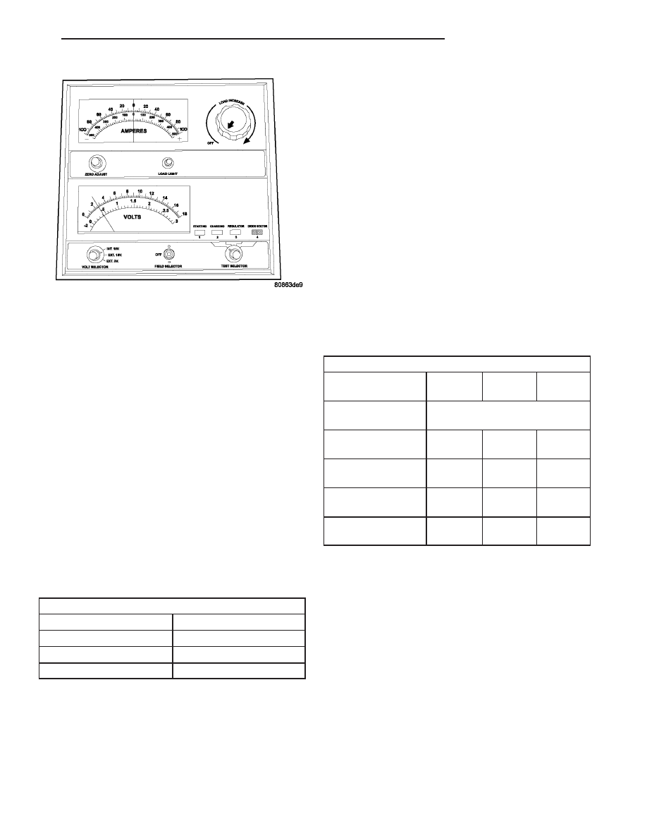
Fig. 4 VOLTMETER ACCURATE TO 1/10 VOLT

VA

BATTERY SYSTEM

8F - 9

(3) Using a voltmeter connected to the battery

posts (see the instructions provided by the manufac-
turer of the voltmeter), measure the open-circuit volt-
age (Fig. 5).

See the Open-Circuit Voltage Table. This voltage

reading will indicate the battery state-of-charge, but
will not reveal its cranking capacity. If a battery has
an open-circuit voltage reading of 12.4 volts or
greater, it may be load tested to reveal its cranking
capacity (Refer to 8 - ELECTRICAL/BATTERY SYS-
TEM/BATTERY - STANDARD PROCEDURE).

OPEN CIRCUIT VOLTAGE TABLE

Open Circuit Voltage

Charge Percentage

11.7 volts or less

0%

12.0 volts

25%

12.2 volts

50%

12.4 volts

75%

12.6 volts or more

100%

STANDARD PROCEDURE - IGNITION - OFF
DRAW TEST

The term Ignition-Off Draw (IOD) identifies a nor-

mal condition where power is being drained from the
battery with the ignition switch in the Off position. A
normal vehicle electrical system will draw from five
to thirty-five milliamperes (0.005 to 0.035 ampere)
with the ignition switch in the Off position, and all
non-ignition controlled circuits in proper working
order. Up to thirty-five milliamperes are needed to
enable the memory functions for the Powertrain Con-
trol Module (PCM), digital clock, electronically tuned
radio, and other modules which may vary with the
vehicle equipment.

A vehicle that has not been operated for approxi-

mately twenty days, may discharge the battery to an
inadequate level. When a vehicle will not be used for
twenty days or more (stored), remove the IOD fuse
from the fuseblock. This will reduce battery discharg-
ing.

Excessive IOD can be caused by:
• Electrical items left on.
• Faulty or improperly adjusted switches.
• Faulty or shorted electronic modules and compo-

nents.

• An internally shorted generator.
• Intermittent shorts in the wiring.
If the IOD is over thirty-five milliamperes, the

problem must be found and corrected before replac-
ing a battery. In most cases, the battery can be
charged and returned to service after the excessive
IOD condition has been corrected.

(1) Verify that all electrical accessories are off.

Turn off all lamps, remove the ignition key, and close
all doors. If the vehicle is equipped with an illumi-
nated entry system or an electronically tuned radio,
allow the electronic timer function of these systems
to automatically shut off (time out). This may take
up to three minutes.

(2) Determine that the underhood lamp is operat-

ing properly, then disconnect the lamp wire harness
connector or remove the lamp bulb.

(3) Disconnect the battery negative cable.
(4) Set an electronic digital multi-meter to its

highest amperage scale. Connect the multi-meter
between the disconnected battery negative cable ter-
minal clamp and the battery negative terminal post.
Make sure that the doors remain closed so that the
illuminated entry system is not activated. The multi-
meter amperage reading may remain high for up to
three minutes, or may not give any reading at all
while set in the highest amperage scale, depending
upon the electrical equipment in the vehicle. The
multi-meter leads must be securely clamped to the
battery negative cable terminal clamp and the bat-
tery negative terminal post. If continuity between the
battery negative terminal post and the negative cable
terminal clamp is lost during any part of the IOD
test, the electronic timer function will be activated
and all of the tests will have to be repeated.

(5) After about three minutes, the high-amperage

IOD reading on the multi-meter should become very
low or nonexistent, depending upon the electrical
equipment in the vehicle. If the amperage reading
remains high, remove and replace each fuse or circuit
breaker in the Fuse Blocks, one at a time until the
amperage reading becomes very low, or nonexistent.
Refer to the appropriate wiring information in this
service manual for complete fuseblock fuse, circuit
breaker, and circuit identification. This will isolate

Fig. 5 Testing Open Circuit Voltage

8F - 10

BATTERY SYSTEM

VA

each circuit and identify the circuit that is the source
of the high-amperage IOD. If the amperage reading
remains high after removing and replacing each fuse
and circuit breaker, disconnect the wire harness from
the generator. If the amperage reading now becomes
very low or nonexistent, refer to Charging System for
the proper charging system diagnosis and testing
procedures. After the high-amperage IOD has been
corrected, switch the multi-meter to progressively
lower amperage scales and, if necessary, repeat the
fuse and circuit breaker remove-and-replace process
to identify and correct all sources of excessive IOD. It
is now safe to select the lowest milliampere scale of
the multi-meter to check the low-amperage IOD.

CAUTION: Do not open any doors, or turn on any
electrical accessories with the lowest milliampere
scale selected, or the multi-meter may be damaged.

(6) Observe the multi-meter reading. The low-am-

perage IOD should not exceed thirty-five milliam-
peres (0.035 ampere). If the current draw exceeds
thirty-five milliamperes, isolate each circuit using the
fuse and circuit breaker remove-and-replace process
in Step 5. The multi-meter reading will drop to
within the acceptable limit when the source of the
excessive current draw is disconnected. Repair this
circuit as required; whether a wiring short, incorrect
switch adjustment, or a component failure is at fault.

STANDARD PROCEDURE - USING MICRO 420
BATTERY TESTER

Always use the Micro 420 Instruction Manual that

was supplied with the tester as a reference. If the

Instruction Manual is not available the following pro-
cedure can be used:

WARNING: ALWAYS

WEAR APPROPRIATE

EYE

PROTECTION AND USE EXTREME CAUTION WHEN
WORKING WITH BATTERIES.

BATTERY TESTING

(1) If testing the battery OUT-OF-VEHICLE, clean

the battery terminals with a wire brush before test-
ing. If the battery is equipped with side post termi-
nals, install and tighten the supplied lead terminal
stud adapters. Do not use steel bolts. Failure to prop-
erly install the stud adapters, or using stud adapters
that are dirty or worn-out may result in false test
readings.

(2) If testing the battery IN-THE-VEHICLE, make

certain all of the vehicle accessory loads are OFF,
including the ignition. The preferred test position
is at the battery terminal
. If the battery is not
accessible, you may test using both the positive and
negative jumper posts. Select TESTING AT JUMPER
POST when connecting to that location.

(3) Connect the tester (Fig. 6) to the battery or

jumper posts, the red clamp to positive (+) and the
black clamp to negative (–).

NOTE: Multiple batteries connected in parallel must
have the ground cable disconnected to perform a
battery test. Failure to disconnect may result in
false battery test readings.

(4) Using the ARROW key select in or out of vehi-

cle testing and press ENTER to make a selection.

(5) If not selected, choose the Cold Cranking Amp

(CCA) battery rating. Or select the appropriate bat-
tery rating for your area (see menu). The tester will
then run its self programmed test of the battery and
display the results. Refer to the test result table
noted below.

CAUTION: If REPLACE BATTERY is the result of the
test, this may mean a poor connection between the
vehicle’s cables and battery exists. After discon-
necting the vehicle’s battery cables from the bat-
tery, retest the battery using the OUT-OF-VEHICLE
test before replacing.

(6) While viewing the battery test result, press the

CODE button and the tester will prompt you for the
last 4 digits of the VIN. Use the UP/DOWN arrow
buttons to scroll to the correct character; then press
ENTER to select and move to the next digit. Then
press the ENTER button to view the SERVICE
CODE. Pressing the CODE button a second time will
return you to the test results.

Fig. 6 Micro 420 Battery Tester

VA

BATTERY SYSTEM

8F - 11

BATTERY TEST RESULTS

GOOD BATTERY

Return to service

GOOD - RECHARGE

Fully charge battery and

return to service

CHARGE & RETEST

Fully charge battery and

retest battery

REPLACE BATTERY

Replace the battery and

retest complete system

BAD-CELL REPLACE

Replace the battery and

retest complete system

NOTE: The SERVICE CODE is required on every
warranty claim submitted for battery replacement.

STANDARD PROCEDURE - CHECKING BATTERY
ELECTROLYTE LEVEL

(1) Remove the battery cell caps (Fig. 7).

(2) Look through the battery cap holes to deter-

mine the level of the electrolyte in the battery (Fig.
8). The electrolyte should be approximately 1 centi-
meter above the battery plates or until the hook
inside the battery cap holes is covered.

(3) Add only distilled water until the electrolyte

level is approx. one centimeter above the plates.

REMOVAL

UNDER HOOD BATTERY REMOVAL

(1) Turn the ignition switch to the Off position. Be

certain that all electrical accessories are turned off.

(2) Loosen the battery negative cable terminal

clamp pinch-bolt hex nut.

(3) Disconnect the battery negative cable terminal

clamp from the battery negative terminal post. If
necessary, use a battery terminal puller to remove
the terminal clamp from the battery post.

(4) Loosen the battery positive cable terminal

clamp pinch-bolt hex nut.

(5) Disconnect the battery positive cable terminal

clamp from the battery positive terminal post. If nec-
essary, use a battery terminal puller to remove the
terminal clamp from the battery post.

(6) Remove the battery hold downs from the bat-

tery (Refer to 8 - ELECTRICAL/BATTERY SYSTEM/
BATTERY HOLDDOWN - REMOVAL).

WARNING: WEAR A SUITABLE PAIR OF RUBBER
GLOVES (NOT THE HOUSEHOLD TYPE) WHEN
REMOVING

A

BATTERY

BY

HAND.

SAFETY

GLASSES SHOULD ALSO BE WORN. IF THE BAT-
TERY IS CRACKED OR LEAKING, THE ELECTRO-
LYTE CAN BURN THE SKIN AND EYES.

(7) Remove the battery from the battery tray.

Fig. 7 Battery Cell Caps

1 - BATTERY CELL CAP
2 - BATTERY

Fig. 8 Hook Inside Battery Cap Holes

1 - BATTERY SURFACE COVER
2 - HOOK

8F - 12

BATTERY SYSTEM

VA


Content   ..  207  208  209  210   ..