Mercedes-Benz Sprinter / Dodge Sprinter. Manual - part 208


  Index      Mercedes     Mercedes-Benz Sprinter / Dodge Sprinter - service repair manual 2006 year


Search            


Content   ..  206  207  208  209   ..


Mercedes-Benz Sprinter / Dodge Sprinter. Manual - part 208


CLEANING

The following information details the recommended

cleaning procedures for the battery and related com-
ponents. In addition to the maintenance schedules
found in this service manual and the owner’s man-
ual, it is recommended that these procedures be per-
formed any time the battery or related components
must be removed for vehicle service.

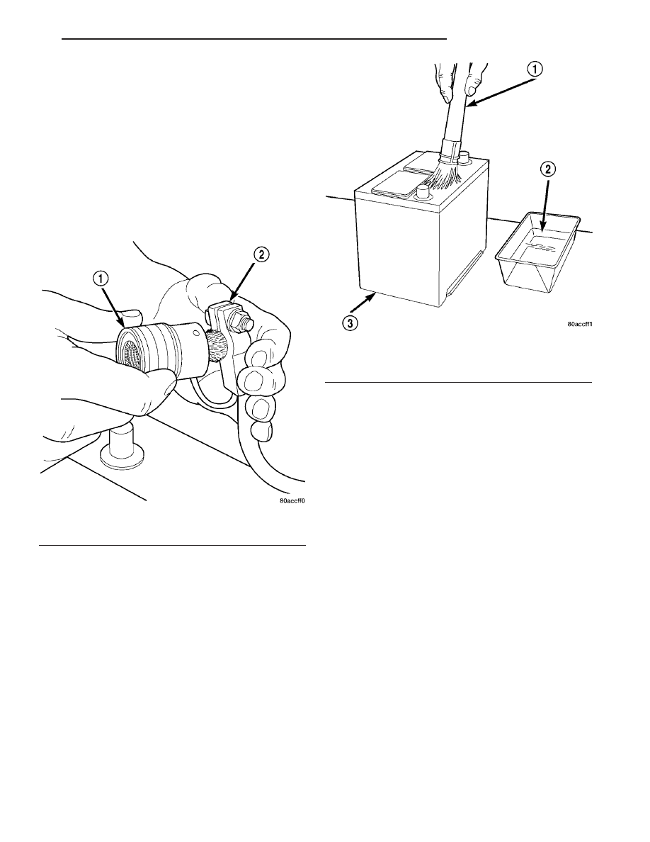
(1) Clean the battery cable terminal clamps of all

corrosion. Remove any corrosion using a wire brush
or a post and terminal cleaning tool, and a sodium
bicarbonate (baking soda) and warm water cleaning
solution (Fig. 1).

(2) Clean the battery tray and battery hold down

hardware of all corrosion. Remove any corrosion
using a wire brush and a sodium bicarbonate (baking
soda) and warm water cleaning solution. Paint any
exposed bare metal.

(3) If the removed battery is to be reinstalled,

clean the outside of the battery case and the top
cover with a sodium bicarbonate (baking soda) and
warm water cleaning solution using a stiff bristle
parts cleaning brush to remove any acid film (Fig. 2).
Rinse the battery with clean water. Ensure that the
cleaning solution does not enter the battery cells
through the vent holes. If the battery is being
replaced, refer to Battery System Specifications for
the factory-installed battery specifications. Confirm
that the replacement battery is the correct size and
has the correct ratings for the vehicle.

(4) If the vehicle is so equipped, clean the battery

thermal guard with a sodium bicarbonate (baking
soda) and warm water cleaning solution using a stiff
bristle parts cleaning brush to remove any acid film.

(5) Clean any corrosion from the battery terminal

posts with a wire brush or a post and terminal
cleaner, and a sodium bicarbonate (baking soda) and
warm water cleaning solution (Fig. 3).

Fig. 1 Clean Battery Cable Terminal Clamp - Typical

1 - TERMINAL BRUSH
2 - BATTERY CABLE

Fig. 2 Clean Battery - Typical

1 - CLEANING BRUSH
2 - WARM WATER AND BAKING SODA SOLUTION
3 - BATTERY

VA

BATTERY SYSTEM

8F - 5

INSPECTION

The following information details the recommended

inspection procedures for the battery and related
components. In addition to the maintenance sched-
ules found in this service manual and the owner’s
manual, it is recommended that these procedures be
performed any time the battery or related compo-
nents must be removed for vehicle service.

(1) Inspect the battery cable terminal clamps for

damage. Replace any battery cable that has a dam-
aged or deformed terminal clamp.

(2) Inspect the battery tray and battery holddown

hardware for damage. Replace any damaged parts.

(3) Slide the thermal guard off of the battery case,

if equipped. Inspect the battery case for cracks or
other damage that could result in electrolyte leaks.
Also, check the battery terminal posts for looseness.
Batteries with damaged cases or loose terminal posts
must be replaced.

(4) Inspect the battery thermal guard for tears,

cracks, deformation or other damage. Replace any
battery thermal guard that has been damaged.

(5) Inspect the battery built-in test indicator sight

glass for an indication of the battery condition. If the
battery is discharged, charge as required. (Refer to 8
-

ELECTRICAL/BATTERY

SYSTEM/BATTERY

-

STANDARD PROCEDURE).

SPECIAL TOOLS

BATTERY SYSTEM SPECIAL TOOLS

BATTERY

DESCRIPTION

Large capacity, low-maintenance storage batteries

are standard factory-installed equipment on this
model. The primary battery is located in the engine
compartment on all models. A second auxiliary bat-
tery may be installed under the passengers front seat
for running additional electrical equipment.

Male post type terminals made of a soft lead mate-

rial protrude from the top of the molded plastic bat-
tery case to provide the means for connecting the
battery to the vehicle electrical system. The battery
positive terminal post is physically larger in diameter
than the negative terminal post to ensure proper bat-
tery connection. The letters POS and NEG are also
molded into the top of the battery case adjacent to
their respective positive and negative terminal posts
for identification confirmation. Refer to Battery
Cables for more information on the battery cables
that connect the battery to the vehicle electrical sys-
tem.

The battery is made up of six individual cells that

are connected in series. Each cell contains positively
charged plate groups that are connected with lead
straps to the positive terminal post, and negatively
charged plate groups that are connected with lead
straps to the negative terminal post. Each plate con-
sists of a stiff mesh framework or grid coated with
lead dioxide (positive plate) or sponge lead (negative

Fig. 3 Clean Battery Terminal Post - Typical

1 - TERMINAL BRUSH
2 - BATTERY CABLE
3 - BATTERY

Micro 420 Battery Tester

8F - 6

BATTERY SYSTEM

VA

plate). Insulators or plate separators made of a non-
conductive material are inserted between the positive
and negative plates to prevent them from contacting
or shorting against one another. These dissimilar
metal plates are submerged in a sulfuric acid and
water solution called an electrolyte.

The factory-installed low-maintenance bat-

tery has removable battery cell caps. Water can
be added to this battery. The chemical composition of
the metal coated plates within the low-maintenance
battery reduces battery gassing and water loss, at
normal charge and discharge rates. Therefore, the
battery should not require additional water in nor-
mal service. Rapid loss of electrolyte can be caused
by an overcharging condition. Be certain to diagnose
the charging system before returning the vehicle to
service.

OPERATION

The battery is designed to store electrical energy in

a chemical form. When an electrical load is applied to
the terminals of the battery, an electrochemical reac-
tion occurs. This reaction causes the battery to dis-
charge electrical current from its terminals. As the
battery discharges, a gradual chemical change takes
place within each cell. The sulfuric acid in the elec-
trolyte combines with the plate materials, causing
both plates to slowly change to lead sulfate. At the
same time, oxygen from the positive plate material
combines with hydrogen from the sulfuric acid, caus-
ing the electrolyte to become mainly water. The
chemical changes within the battery are caused by
the movement of excess or free electrons between the
positive and negative plate groups. This movement of
electrons

produces

a

flow

of

electrical

current

through the load device attached to the battery ter-
minals.

As the plate materials become more similar chem-

ically, and the electrolyte becomes less acid, the volt-
age potential of each cell is reduced. However, by
charging the battery with a voltage higher than that
of the battery itself, the battery discharging process
is reversed. Charging the battery gradually changes
the sulfated lead plates back into sponge lead and
lead dioxide, and the water back into sulfuric acid.
This action restores the difference in the electron
charges deposited on the plates, and the voltage
potential of the battery cells. For a battery to remain
useful, it must be able to produce high-amperage cur-
rent over an extended period. A battery must also be
able to accept a charge, so that its voltage potential
may be restored.

The battery is vented to release excess hydrogen

gas that is created when the battery is being charged
or discharged. However, even with these vents,
hydrogen gas can collect in or around the battery. If
hydrogen gas is exposed to flame or sparks, it may
ignite. If the electrolyte level is low, the battery may

arc internally and explode. If the battery is equipped
with removable cell caps, add distilled water when-
ever the electrolyte level is below the top of the
plates. If the battery cell caps cannot be removed, the
battery must be replaced if the electrolyte level
becomes low.

DIAGNOSIS AND TESTING - BATTERY

The battery must be completely charged and the

terminals should be properly cleaned and inspected
before diagnostic procedures are performed. Refer to
Battery System Cleaning for the proper cleaning pro-
cedures, and Battery System Inspection for the
proper battery inspection procedures. Refer to Stan-
dard Procedures for the proper battery charging pro-
cedures.

MICRO 420 BATTERY TESTER

The

Micro

420

automotive

battery

tester

is

designed to help the dealership technicians diagnose
the cause of a defective battery. Follow the instruc-
tion manual supplied with the tester to properly
diagnose a vehicle. If the instruction manual is not
available refer to the standard procedure in this sec-
tion, which includes the directions for using the
Micro 420 battery tester.

WARNING: IF THE BATTERY SHOWS SIGNS OF
FREEZING, LEAKING OR LOOSE POSTS, DO NOT
TEST, ASSIST-BOOST, OR CHARGE. THE BATTERY
MAY ARC INTERNALLY AND EXPLODE. PERSONAL
INJURY AND/OR VEHICLE DAMAGE MAY RESULT.

WARNING: EXPLOSIVE HYDROGEN GAS FORMS IN
AND AROUND THE BATTERY. DO NOT SMOKE,
USE FLAME, OR CREATE SPARKS NEAR THE BAT-
TERY. PERSONAL INJURY AND/OR VEHICLE DAM-
AGE MAY RESULT.

WARNING: THE BATTERY CONTAINS SULFURIC
ACID, WHICH IS POISONOUS AND CAUSTIC. AVOID
CONTACT WITH THE SKIN, EYES, OR CLOTHING.
IN THE EVENT OF CONTACT, FLUSH WITH WATER
AND CALL A PHYSICIAN IMMEDIATELY. KEEP OUT
OF THE REACH OF CHILDREN.

A battery that will not accept a charge is faulty,

and

must

be

replaced.

Further

testing

is

not

required. A fully-charged battery must be tested to
determine its cranking capacity. A battery that is ful-
ly-charged, but does not pass the Micro 420 or load
test, is faulty and must be replaced.

NOTE: Completely discharged batteries may take
several hours to accept a charge. Refer to Standard
Procedures for the proper battery charging proce-
dures.

VA

BATTERY SYSTEM

8F - 7

STANDARD PROCEDURE

STANDARD PROCEDURE - BATTERY CHARG-
ING

Battery charging is the means by which the bat-

tery can be restored to its full voltage potential. A
battery is fully-charged when:

• Micro 420 electrical system tester indicates bat-

tery is OK.

• Three hydrometer tests, taken at one-hour inter-

vals, indicate no increase in the temperature-cor-
rected specific gravity of the battery electrolyte.

• Passes Load test.

• Open-circuit voltage of the battery is 12.65 volts

or above.

WARNING: IF THE BATTERY SHOWS SIGNS OF
FREEZING, LEAKING OR LOOSE POSTS, DO NOT
TEST, ASSIST-BOOST, OR CHARGE. THE BATTERY
MAY ARC INTERNALLY AND EXPLODE. PERSONAL
INJURY AND/OR VEHICLE DAMAGE MAY RESULT.

WARNING: EXPLOSIVE HYDROGEN GAS FORMS IN
AND AROUND THE BATTERY. DO NOT SMOKE,
USE FLAME, OR CREATE SPARKS NEAR THE BAT-
TERY. PERSONAL INJURY AND/OR VEHICLE DAM-
AGE MAY RESULT.

WARNING: THE BATTERY CONTAINS SULFURIC
ACID, WHICH IS POISONOUS AND CAUSTIC. AVOID
CONTACT WITH THE SKIN, EYES, OR CLOTHING.
IN THE EVENT OF CONTACT, FLUSH WITH WATER
AND CALL A PHYSICIAN IMMEDIATELY. KEEP OUT
OF THE REACH OF CHILDREN.

WARNING: IF THE BATTERY IS EQUIPPED WITH
REMOVABLE CELL CAPS, BE CERTAIN THAT EACH
OF THE CELL CAPS IS IN PLACE AND TIGHT
BEFORE THE BATTERY IS RETURNED TO SER-
VICE. PERSONAL INJURY AND/OR VEHICLE DAM-
AGE MAY RESULT FROM LOOSE OR MISSING
CELL CAPS.

CAUTION: Always disconnect and isolate the bat-
tery negative cable before charging a battery. Do
not exceed sixteen volts while charging a battery.
Damage to the vehicle electrical system compo-
nents may result.

CAUTION: Battery electrolyte will bubble inside the
battery case during normal battery charging. Elec-
trolyte boiling or being discharged from the battery
vents indicates a battery overcharging condition.
Immediately reduce the charging rate or turn off the

charger to evaluate the battery condition. Damage
to the battery may result from overcharging.

CAUTION: The battery should not be hot to the
touch. If the battery feels hot to the touch, turn off
the charger and let the battery cool before continu-
ing the charging operation. Damage to the battery
may result.

Some battery chargers are equipped with polarity-

sensing circuitry. This circuitry protects the battery
charger and the battery from being damaged if they
are improperly connected. If the battery state-of-
charge is too low for the polarity-sensing circuitry to
detect, the battery charger will not operate. This
makes it appear that the battery will not accept
charging current. See the instructions provided by
the manufacturer of the battery charger for details
on how to bypass the polarity-sensing circuitry.

After the battery has been charged to 12.4 volts or

greater, retest the battery using the Micro 420 tester
or perform a load test to determine the battery
cranking capacity. If the battery will endure a load
test, return the battery to service. If the battery will
not endure a load test, it is faulty and must be
replaced.

Clean and inspect the battery hold downs, tray,

terminals, posts, and top before completing battery
service. Refer to Battery System Cleaning for the
proper battery system cleaning procedures, and Bat-
tery System Inspection for the proper battery system
inspection procedures.

CHARGING A COMPLETELY DISCHARGED BAT-
TERY

The following procedure should be used to recharge

a completely discharged battery. Unless this proce-
dure is properly followed, a good battery may be
needlessly replaced.

(1) Measure the voltage at the battery posts with a

voltmeter, accurate to 1/10 (0.10) volt (Fig. 4). If the
reading is below ten volts, the battery charging cur-
rent will be low. It could take some time before the
battery accepts a current greater than a few milliam-
peres. Such low current may not be detectable on the
ammeters built into many battery chargers.

8F - 8

BATTERY SYSTEM

VA


Content   ..  206  207  208  209   ..