Mercedes-Benz Sprinter / Dodge Sprinter. Manual - part 187


  Index      Mercedes     Mercedes-Benz Sprinter / Dodge Sprinter - service repair manual 2006 year


Search            


Content   ..  185  186  187  188   ..


Mercedes-Benz Sprinter / Dodge Sprinter. Manual - part 187


(13) Connect propeller shaft to pinion flange.

NOTE: On dual rear wheel axle install axle shafts.

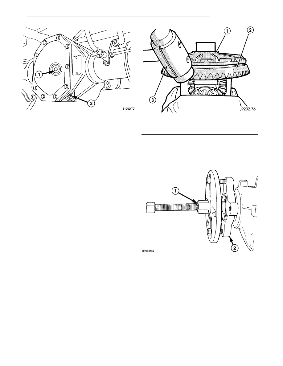
(14) Pour in oil up to bottom edge of oil filler hole

(1) (Fig. 63).

(15) Screw in oil filler plug (1) and tighten to 100

N·m (74 ft. lbs.).

(16) Install wheels at rear axle.
(17) Operate brake pedal several times until brake

pads contact brake discs (brake pressure built up).

(18) Attach rear brake cables if removed and

adjust parking brake.

GEAR - PINION / RING

REMOVAL

NOTE: The ring and pinion gears are serviced in a
matched set. Never replace one gear without replac-
ing the other gear.

(1) Remove differential from housing.
(2) Place differential case in a vise with soft metal

jaw.

(3) Remove ring gear bolts from the differential

case.

(4) Drive ring gear off the differential case with a

dead-blow hammer (Fig. 64).

(5) Unlock collared nut.
(6) Hold pinion flange with Flange Wrench C-3281

and remove nut.

(7) Remove pinion flange from pinion shaft with

Puller 8892 and Wrench C-3281 (Fig. 65).

(8) Remove pinion gear from housing with a dead-

blow hammer.

(9) Remove pinion shaft seal with a seal pick.
(10) Remove front pinion bearing.
(11) Remove

front

pinion

bearing

cup

with

Remover D-103 and Handle C-4171.

(12) Remove rear pinion bearing cup with Remover

9084 and Handle C-4171.

(13) Remove pinion depth shim from rear pinion

bearing cup bore.

(14) Remove collapsible spacer (Fig. 66).

Fig. 63 FILL PLUG

1 - FILL PLUG
2 - DRAIN PLUG

Fig. 64 RING GEAR

1 - CASE
2 - RING GEAR
3 - DEAD-BLOW HAMMER

Fig. 65 FLANGE PULLER

1 - FLANGE PULLER
2 - PINION FLANGE

VA

REAR AXLE

3 - 41

(15) Remove spacer from pinion shaft (Fig. 67).

(16) Remove rear bearing from pinion shaft with

Puller/Press C-293-PA and Adapters C-293-47 (Fig.
68).

INSTALLATION

(1) Apply Mopar Door Ease or equivalent lubricant

to outside surface of bearing cups.

(2) Install pinion depth shim in rear pinion bear-

ing cup bore.

(3) Install rear pinion bearing cup with Installer

C-4310 and Driver Handle C-4171.

(4) Install front pinion bearing cup with Installer

8617 and Handle C-4171.

(5) Install rear bearing on pinion with Installer

MB-998805 and a press (Fig. 69).

Fig. 66 COLLAPSIBLE SPACER

1 - COLLAPSIBLE SPACER
2 - SPACER

Fig. 67 SPACER

1 - SPACER
2 - PINION SHAFT

Fig. 68 Rear Bearing Removal

1 - PULLER
2 - VISE
3 - ADAPTERS
4 - DRIVE PINION GEAR SHAFT

3 - 42

REAR AXLE

VA

(6) Install pinion spacer on pinion shaft (Fig.

70).

(7) Install new collapsible preload spacer on pin-

ion shaft (Fig. 71) and install pinion gear into the
housing.

(8) Install front pinion bearing into housing with

Installer 9548.

(9) Apply a light coating of gear lubricant on the

lip of pinion seal and install seal with Installer 9276
(Fig. 72).

(10) Hold

pinion

flange

with

Flange

Wrench

C-3281.

(11) Screw on the new collared nut.
(12) Tighten collar nut carefully to a torque to

rotate of 2.5-3 N·m (22-27 in. lbs.).

(13) Cut the collar of the tightened collared nut

(Fig. 73).

Fig. 69 REAR BEARING INSTALLATION

1 - PRESS
2 - INSTALLER
3 - DRIVE PINION GEAR
4 - REAR PINION BEARING

Fig. 70 SPACER

1 - SPACER
2 - PINION SHAFT

Fig. 71 COLLAPSIBLE SPACER

1 - COLLAPSIBLE SPACER
2 - SPACER

Fig. 72 PINION SEAL INSTALLER

1 - AXLE
2 - INSTALLER

VA

REAR AXLE

3 - 43

(14) Bend collar so it touches the wall of the slot

in the pinion shaft (Fig. 74).

(15) Invert differential case and start two ring

gear bolts. This will provide case-to-ring gear bolt
hole alignment.

(16) Invert differential case in the vise and install

new ring gear bolts and alternately tighten to 180
N.m (133 ft. lbs.) (Fig. 75)

CAUTION: Do not reuse ring gear bolts, the bolts
can fracture causing extensive damage. Failure to
heed caution may result in damage.

(17) Install differential in axle housing and verify

gear mesh and contact pattern.

Fig. 73 COLLARED NUT

Fig. 74 BEND COLLAR OF NUT

1 - COLLARED NUT
2 - DRIFT

Fig. 75 RING GEAR

1 - TORQUE WRENCH
2 - RING GEAR BOLT
3 - RING GEAR
4 - CASE

3 - 44

REAR AXLE

VA


Content   ..  185  186  187  188   ..