Mercedes-Benz Sprinter / Dodge Sprinter. Manual - part 186


  Index      Mercedes     Mercedes-Benz Sprinter / Dodge Sprinter - service repair manual 2006 year


Search            


Content   ..  184  185  186  187   ..


Mercedes-Benz Sprinter / Dodge Sprinter. Manual - part 186


(5) Install differential cover (2) bolts (1) and tighen

to 45 N·m (33 ft. lbs.) (Fig. 52).

INSTALLATION

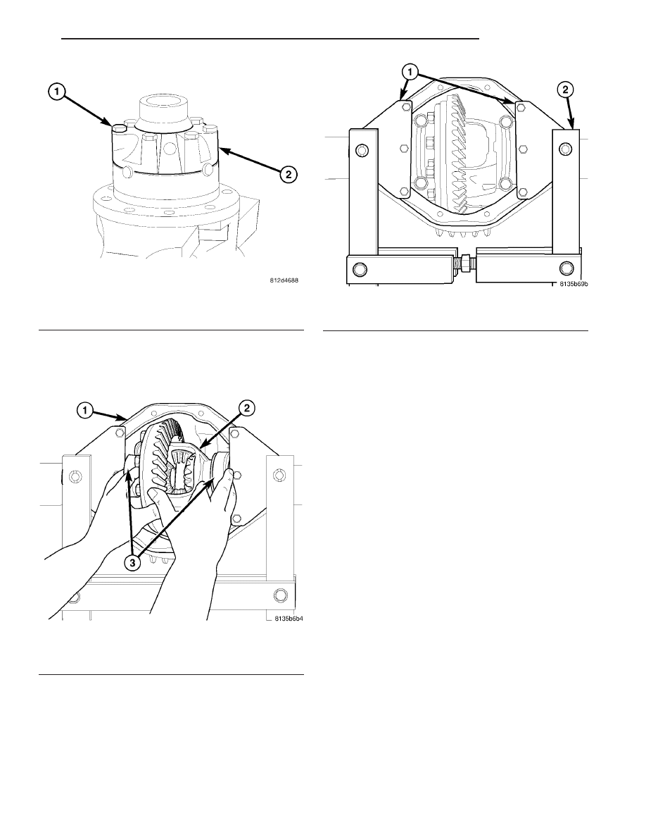
(1) Spread the differential housing (1).

CAUTION: Never spread over 0.3 mm (0.011 in). If
the housing is over-spread, it could be distorted or
damaged.

(2) Install differential case (2) into the housing (1)

with bearings, cups (3) and shims (Fig. 53).

(3) Loosely install differential bearing cap bolts.

(4) Remove spreader (2) and adapters (1) from

housing (Fig. 54).

(5) Tighten bearing cap bolts to 70 N·m (52 ft.

lbs.).

(6) Install axle shafts.
(7) Install differential cover and tighten bolts to 65

N·m (48 ft. lbs.).

(8) Fill differential housing with lubricant.

Fig. 52 DIFFERENTIAL COVER

1 - BOLTS
2 - COVER

Fig. 53 DIFFERENTIAL INSTALLATION

1 - HOUSING
2 - DIFFERENTIAL
3 - DIFFERENTIAL BEARINGS

Fig. 54 SPREADER

1 - ADAPTERS
2 - SPREADER

VA

REAR AXLE

3 - 37

BEARINGS - DIFFERENTIAL
CASE

REMOVAL

(1) Remove

differential

bearings

with

Puller

C-293-PA (1), Plug C-293-3 (2) and four Adapters
C-293-37 (3) (Fig. 55).

INSTALLATION

(1) Set differential on Plug C-293-3.
(2) Install

differential

(2)

bearings

(3)

with

Installer 9523 (4) and Handle C-4171 (1) (Fig. 56).

(3) Install differential case in axle.

Fig. 55 CASE BEARING PULLER

1 - PULLER
2 - PLUG
3- ADAPTERS

Fig. 56 DIFFERENTIAL BEARINGS

1 - HANDLE
2 - DIFFERENTIAL
3 - BEARING
4 - INSTALLER

3 - 38

REAR AXLE

VA

SEAL - PINION

REMOVAL

(1) Remove wheels.
(2) Push back brake pads and release hand brake.

NOTE: If it is not possible to spin rear axle shafts
manually, detach rear brake cables.

(3) Drain rear axle oil.

NOTE: On dual rear wheel axle remove axle shafts.

(4) Remove propeller shaft.
(5) Spin pinion flange by hand and check axial

play of bearing.

CAUTION: There must not be any thrust bearing
play. If play excess or there are particles (shavings)
in the drained oil, replace gear assembly.

(6) Measure and record torque to rotate the pinion.
(7) Mark pinion position to pinion flange (1) (Fig.

57).

(8) Unlock collared nut.
(9) Hold pinion flange (1) with Flange Wrench

C-3281 and remove nut.

(10) Remove pinion flange (1) from pinion shaft

with Flange Puller 8992 (2) (Fig. 58).

(11) Check sealing surfaces of joint flange for score

marks and replace joint flange if necessary.

(12) Remove pinion seal/seals (1) (Fig. 59).

Fig. 57 COLLARED NUT

1 - PINION FLANGE
2 - COLLARED NUT

Fig. 58 FLANGE PULLER

1 - FLANGE PULLER
2 - PINION FLANGE

Fig. 59 PINION SEALS

1 - SEALS
2 - AXLE

VA

REAR AXLE

3 - 39

INSTALLATION

(1) Pack space between dust lip and sealing lip on

seal ring with multi-purpose grease.

(2) On seals without rubberized external surface,

coat outer circumference with sealant.

CAUTION: Do not coat partially rubberized seals
with sealant.

(3) Drive new pinion seal/seals into rear axle

housing as far as the stop using Installer 9276 (2)
(Fig. 60).

(4) Fit coupling flange on drive pinion shaft.

NOTE: The groove in the drive pinion and the
groove in the joint flange must be in alignment.

(5) Hold pinion flange with Flange Wrench C-3281.
(6) Tighten collar nut to 100 N·m. (74 ft. lbs.).
(7) Using a dial indicator check free play at pinion

flange.

NOTE: Should bearing not be free of play, tighten in
increases of 10 N·m. (88 in. lbs.) to maximun of 130
N·m. (95 ft. lbs.). If bearing is not free from play at
130 N·m. (95 ft. lbs.) collapsible spacer must be
replaced.

(8) Identify the position of the pinion to the nut

twevle points and mark pinion and nut.

(9) Turn nut pinion nut 30° (one twelve point).

Them rotate pinion thirty times.

(10) Measure torque to rotate. The torque to rotate

must be 0.1-0.2 N·m (0.9-1.7 in. lbs.) higher then
recorded torque.

NOTE: If value is below or above collapsible spacer
must be replaced.

(11) Cut the collar of the collared nut (Fig. 61).

(12) Bend collar nut (1) so it touches the wall of

the slot in the pinion shaft (Fig. 62).

Fig. 60 PINION SEAL INSTALLER

1 - AXLE
2 - INSTALLER

Fig. 61 COLLARED NUT

Fig. 62 BEND COLLAR OF NUT

1 - COLLARED NUT
2 - DRIFT

3 - 40

REAR AXLE

VA


Content   ..  184  185  186  187   ..