Mercedes-Benz Sprinter / Dodge Sprinter. Manual - part 167


  Index      Mercedes     Mercedes-Benz Sprinter / Dodge Sprinter - service repair manual 2006 year


Search            


Content   ..  165  166  167  168   ..


Mercedes-Benz Sprinter / Dodge Sprinter. Manual - part 167


10.2

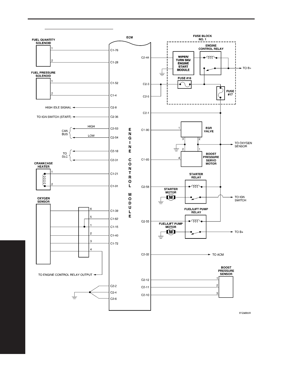
ENGINE CONTROL MODULE

S

C

H

E

M

A

T

I

C

D

I

A

G

R
A

M

S

276

SCHEMATIC DIAGRAMS

11.0

CHARTS AND GRAPHS

C

H

A
R

T
S

A

N

D

G

R
A

P

H

S

277

CHARTS AND GRAPHS

DIAGNOSTIC TEST PROCEDURES — TELL US!

DaimlerChrysler Corporation is constantly working to provide the technician the best diagnostic manuals possible.
Your comments and recommendations regarding the diagnostic manuals and procedures are appreciated.

To best understand your suggestion, please complete the form giving us as much detail as possible.

Model

Year

Body Type

Engine

Transmission

Vehicle Mileage

MDH

Diagnostic Procedure

Book No.

Page

Comments/recommendations (if necessary, draw sketch)

Name

Submitted by:

Address

City/State/Zip

Business Phone #

All comments become property of DaimlerChrysler Corporation and may be used without compensation.

POSITION

INTERPRETATION

CODE = DESCRIPTION

5 & 6

Model, Cab, Weight

D1 = Sprinter, 3000 mm (118 in.) wheelbase, 8,001 up to 9,000
lbs. class G
D2 = Sprinter, 3550 mm (140 in.) wheelbase, 8,001 up to 9,000
lbs. class G
D3 = Sprinter, 4025 mm (158 in.) wheelbase, 8,001 up to 9,000
lbs. class G
D4 = Sprinter, 3550 mm (140 in.) wheelbase, Van 10,001 up to
14,000 lbs. Class H
D5 = Sprinter, 4025 mm (158 in.) wheelbase, Van 10,001 up to
14,000 lbs. Class H
D6 = Sprinter, 3567 mm (140 in.) in connection with 16” wheels,
Van 8,001 to 9,000 lbs. class G
D7 = Sprinter, 4042 mm (159 in.) in connection with 16” wheels,
Van 8,001 to 9,000 lbs. class G

7 & 8

Engine

41 = 2.7L 5 cyl. Diesel 612 (ME9)

42 = 2.7L 5 cyl. Diesel 612 (MF1)

43 = 2.7L 5 cyl. Diesel 647 (MC0)

44 = 2.7L 5 cyl. Diesel 647 (MF2)

9

Check Digit

10

Model Year

6 = 2006

11

Assembly Plant

5 = Düsseldorf Plant, Germany

12 Thru 17

Vehicle Build Sequence

INTERNATIONAL SYMBOLS

DESCRIPTION

The graphic symbols illustrated in the following

International Control and Display Symbols Chart
(Fig. 1) are used to identify various instrument con-
trols. The symbols correspond to the controls and dis-
plays that are located on the instrument panel.

2

INTRODUCTION

VA


Content   ..  165  166  167  168   ..