Mercedes-Benz Sprinter / Dodge Sprinter. Manual - part 76


  Index      Mercedes     Mercedes-Benz Sprinter / Dodge Sprinter - service repair manual 2006 year


Search            


Content   ..  74  75  76  77   ..


Mercedes-Benz Sprinter / Dodge Sprinter. Manual - part 76


11.0

CHARTS AND GRAPHS

11.1

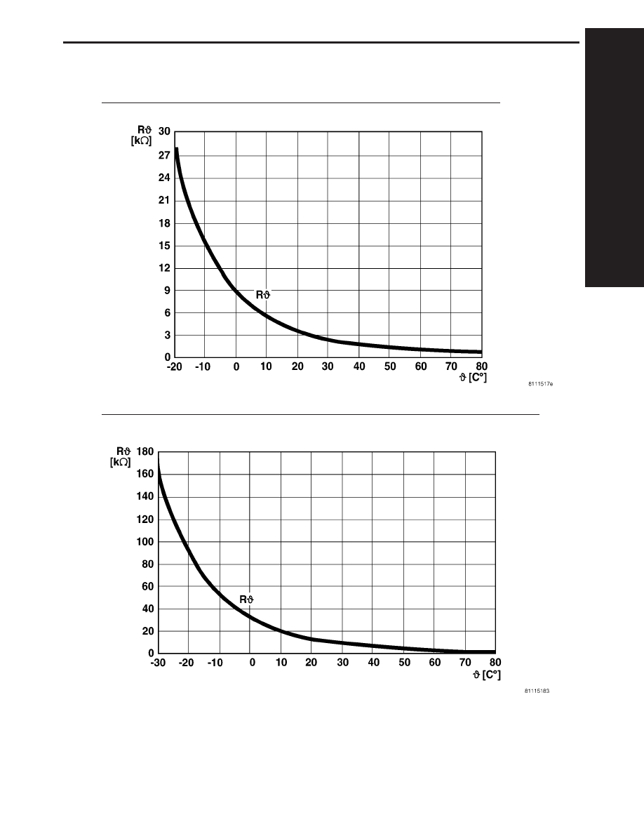
EVAP TEMP SENSOR RESISTANCE TO TEMPERATURE SPECIFICATIONS

11.2

AIR OUTLET TEMP SENSOR RESISTANCE TO TEMPERATURE SPECIFICATIONS

C

H

A
R

T
S

A

N

D

G

R
A

P

H

S

301

CHARTS AND GRAPHS

11.3

WIPER SWITCH/WASHER SWITCH VOLTAGE SIGNALS

C

H

A
R

T
S

A

N

D

G

R
A

P

H

S

302

CHARTS AND GRAPHS

1.0

INTRODUCTION

The procedures contained in this manual include

all the specifications, instructions, and graphics
needed to diagnose the Sprinter Chassis system
problems: Bosch 5.7 ABS/ESP/TCS (ASR) Braking
System. The diagnostics in this manual are based
on the failure condition or symptom being present
at time of diagnosis.

Please follow the recommendations below when

choosing your diagnostic path.

1. First make sure the DRBIII

t is communicating

with the vehicle system being diagnosed. If the
DRBIII

t displays a ‘‘No Response’’ condition, you

must diagnose that first.

2. Read DTC’s (diagnostic trouble codes) with the

DRBIII

t.

3. If no DTC’s are present, identify the customer

complaint.

4. Once the DTC or customer complaint is iden-

tified locate the matching test in the Table of
Contents and begin to diagnose the system.

All component location views are in Section 8.0.

All connector pinouts are in Section 9.0. All sche-
matics are in Section 10.0.

When repairs are required, refer to the appropri-

ate service manual for the proper removal and
repair procedure.

Diagnostic procedures change every year. New

diagnostic systems may be added; carryover sys-
tems maybe enhanced. READ THIS MANUAL BE-
FORE TRYING TO DIAGNOSE A VEHICLE DI-
AGNOSTIC TROUBLE CODE. It is recommended
that you review the entire manual to become famil-
iar with all new and changed diagnostic procedures.

This manual reflects many suggested changes

from readers of past issues. After using this man-
ual, if you have any comments or recommendations,
please fill out the form at the back of the manual
and mail it back.

1.1

SYSTEM COVERAGE

This diagnostic procedure manual covers the An-

tilock Braking System (ABS), the Electronic Stabil-
ity Program (ESP) and the Traction Control System
(TCS) found on the Sprinter.

1.2

SIX-STEP TROUBLESHOOTING
PROCEDURE

Diagnosis of the Antilock Brake Systems is done

in six basic steps:

Verification of complaint

Verification of any related symptoms

Symptom analysis

Problem isolation

Repair of isolated problem

Verification of proper operation

2.0

INDENTIFICATION OF
SYSTEM

The Bosch 5.7 system can be identified by the 42

way Controller Antilock Brake (CAB), Hydraulic
Control Unit (HCU) and Pump Motor being an
integral electronic/hydraulic unit mounted below
the Master Cylinder with four Wheel Speed Sen-
sors, one at each wheel.

Vehicles with the Traction Control System (TCS/

ASR) can be identified by the presence of the
Traction Control System Switch (TCCS) located on
the center instrument panel.

Vehicles with Electronic Stability Program (ESP)

can be identified by the presence of the Steering
Angle Sensor and the Lateral Acceleration/Yaw
Sensor.

3.0

SYSTEM DESCRIPTION AND
FUNCTIONAL OPERATION

3.1

ESP

The ESP system consists of the electronic control/

hydraulic unit, steering angle sensor, lateral
acceleration/yaw sensor and wheel speed sensors.
When the vehicle is in a turn, the ESP looks at the
steering wheel angle sensor value and monitors the
wheel speed of the inner and outer wheels to ensure
the values are plausible. The steering angle sensor
also measures the speed at which the steering
wheel is turned.

The ESP control module is very similar to the

ABS/ASR module. The ESP is comprised of several
other systems, namely the HBA, ABS, TCS (ASR),
EBD 
and FZR systems.

3.2

ABS

The Controller Antilock Brake (CAB) is used to

monitor wheel speeds and modulates (controls) hy-
draulic pressure in each brake channel. The modu-
lated hydraulic pressure is used to prevent wheel
lock up during braking and maintain vehicle stabil-
ity. The CAB also provides a vehicle speed signal
(VSS) to the Electronic Control Module (ECM).
During a non-ABS stop, the system functions as a
standard braking system. The CAB uses special
sortware that monitors the wheel speed(s) and
when certain criteria are met, the software will

1

GENERAL INFORMATION

enable the HCU to perform the brake fluid manage-
ment control as the combination/proportioning
valves.

The Bosch 5.7 system uses the CAB/HCU/Pump

Motor to make an integral electronic/hydraulic unit
which shares data with other electronic modules on
the vehicle via the CAN C Bus network. To access
DTCs from the CAB, the DRBIII

t uses the K-ABS

line located in the Data Link Connector (DLC).

3.3

BRAKE ASSIST SYSTEM (HBA)

The Brake Assist System (HBA) analyzes how

hard and fast the driver wants to brake. It monitors
the brake pressure via a pressure sensor. The
passenger car brake assist system uses a vacuum
booster solenoid. The Sprinter uses the hydraulic
control unit to develop the brake pressure.

3.4

TCS (ASR)

The primary function of the Traction Control System

is to reduce wheel slip and maintain traction at the
driven wheels when the road surfaces are slippery. The
Traction Control System reduces wheel slip by applying
the brake that has lost traction. The system is designed
to operate at speeds below 50 km/h (30 mph). The
engine’s torque can be reduced by the ECM via the CAN
C Bus, if necessary. The TCS can be deactivated with
switch on the dash. The Traction Control System uses
the ABS to indicate spinning tires to enable the traction
control function. The TCS software is in the CAB.

The TCS (ASR) performs the following functions:

1. Engine power derate

2. Engine deceleration regulation. If the vehicle is

on a patch of ice, the simple action of releasing
the throttle is enough to cause the rear wheels to
slip. To avoid this, the throttle input is regulated
so power drops slowly instead of abruptly. The
engine power is reduced (decelerated) as neces-
sary.

3.5

ELECTRONIC BRAKE DISTRIBUTION
(EBD)

The system was enhanced and eliminates the

need for the ALB system (load sensing valve). All
ESP equipped models will not have ALB. The EBV
system self-adapts to operating conditions. It de-
tects the vehicle’s payload when the vehicle starts
and pulls away. Based on the acceleration rate
when the vehicle first pulls away from a standstill,
the system is able to calculate the actual payload.
This is a rough estimate which is used initially.
Later on, the system gathers more precise informa-
tion by monitoring the brake pressure and wheel
speed and negative slip when the driver applies the

brakes. The system will then produce a more accu-
rate calculation of payload depending on brake
retardation. The adaptation is erased when the
ignition is switched off. A new adaptation will occur
on the next driving cycle. By default, the system
acts upon the vehicle as if in an unloaded condition
(safe mode).

Once a new driving cycle begins with the vehicle

in a fully loaded condition (without having gathered
more precise information) the system will detect
ABS actuation in the front wheels and will allow
enough pressure to be applied to the rear axle, to an
extent where the wheels are just about to lock up
(maximum braking possible).

The system calculates the braking force at the

front and rear axles. If the driver applies the brakes
gently and then realizes he needs to apply the
brakes further, the EBV allows the proper pressure
to be applied to the front and rear brakes.

The EBV also contains a feature called “corner

brake system” (CBS) which operates when the ve-
hicle is braked while cornering to avoid a possible
oversteering condition. The EBV monitors the
wheel speed of both rear wheels to detect when the
vehicle is cornering and allows precise brake pres-
sure application to the front and rear brakes. Also
when the brakes are applied during cornering, the
outer wheels get more of the vehicle’s weight while
the inner wheels get less weight and could lose
traction (wheel lock up). The EBV system splits the
pressure between left and right sides in addition to
front and rear brakes.

3.6

VEHICLE CONTROLLING (FZR)

Vehicle controlling (FZR) requires additional

sensors to operate. The term ESP refers to the
software of the system. The term FZR refers to the
system controller. The TCS (ASR) system requires
wheel speed sensors to monitor wheel slip and CAN
bus communications to regulate engine power. In
addition to these inputs, the vehicle controlling
(FZR) requires a steering angle sensor, and a lateral
acceleration/yaw rate sensor.

The ESP system does not take the vehicle load

into account. Instead, the coefficient of friction is
calculated in a 20 millisecond period, where the
controller measures the rate at which the wheel
speed is decelerated, as brake pressure is applied to
the wheel.

3.7

SYSTEM COMPONENTS

Controller Antilock Brake (CAB)

Hydraulic Control Unit (HCU)

Pump Motor

2

GENERAL INFORMATION


Content   ..  74  75  76  77   ..