Mazda MX-30 (2022 year). Manual in english - page 3
Essential Safety Equipment
SRS Air Bags
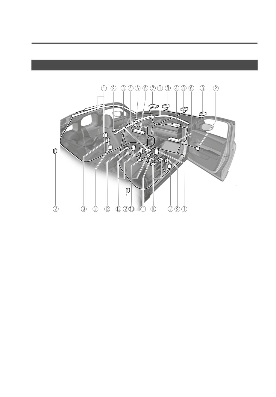
Supplemental Restraint System Components
▼ Supplemental Restraint System Components
1. Side and curtain inflators and air bags
2. Side crash sensors
3. Roll-over sensor, crash sensors, and diagnostic module (SAS unit)
4. Driver/Front passenger inflators and air bags
5. Air bag/front seat belt pretensioner system warning indication/warning light
(page 7-27)
6. Driver/Front passenger knee inflators and air bags
7. Front passenger air bag deactivation indicator light (page 2-64)
8. Front air bag sensors
9. Seat belt pretensioners (page 2-31)
10.Front passenger seat weight sensors (page 2-64)
11.Front passenger seat weight sensor control module
12.Driver and front passenger seat belt buckle switches (page 2-68)
13.Driver seat slide position sensor (page 2-64)
2-57
Essential Safety Equipment
SRS Air Bags
the driver's air bag deploys with lesser
How the SRS Air Bags
energy, whereas during more severe
Work
impacts, it deploys with more energy.
▼ How the SRS Air Bags Work
Your Mazda is equipped with the
following types of SRS air bags. SRS air
bags are designed to work together
with the seat belts to help to reduce
injuries during an accident.
The SRS air bags are designed to
provide further protection for
passengers in addition to the seat belt
functions. Be sure to wear seat belts
properly.
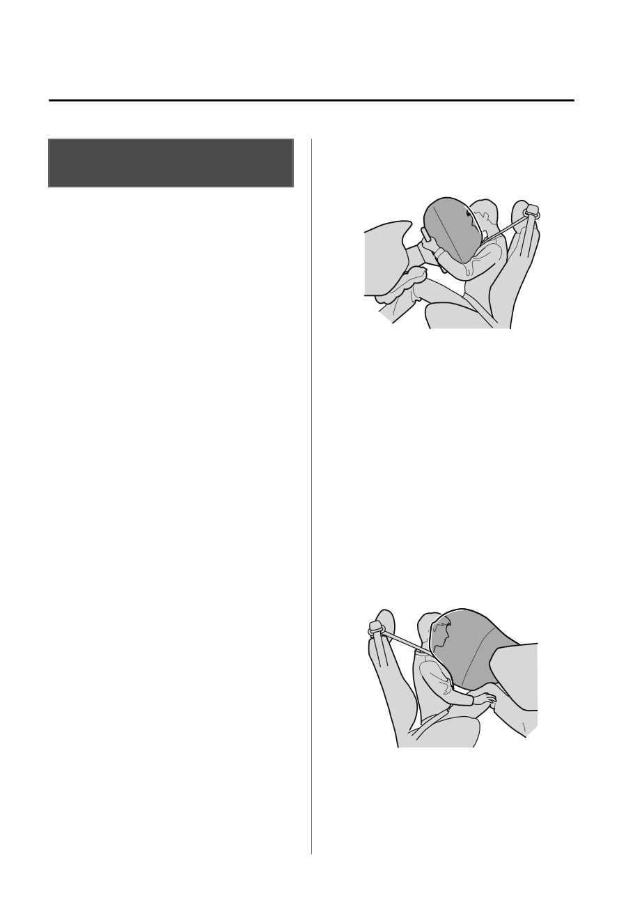
▼ Front Passenger Air Bag
The front passenger air bag is mounted
▼ Front Seat Belt Pretensioners
in the front passenger dashboard.
The front seat belt pretensioners are
The inflation mechanism for the front
designed to deploy in moderate or
passenger air bag is the same as the
severe frontal, near frontal collisions.
driver's air bag.
In addition, the pretensioners operate
For more details about air bag
when a side collision or a roll-over
deployment, refer to "SRS Air Bag
accident is detected. The pretensioners
Deployment Criteria" (page 2-61).
operate differently depending on what
In addition, the front passenger air bag
types of air bags are equipped. For
is designed to only deploy in
more details about seat belt
accordance with the total seated
pretensioner operation, refer to the
weight on the front passenger seat. For
SRS Air Bag Deployment Criteria (page
details, refer to the driver and front
2-61).
passenger occupant classification
system (page 2-64).
▼ Driver Air Bag
The driver's air bag is mounted in the
steering wheel.
When air bag crash sensors detect a
frontal impact of greater than
moderate force, the driver's air bag
inflates quickly helping to reduce injury
mainly to the driver's head or chest
caused by directly hitting the steering
wheel.
For more details about air bag
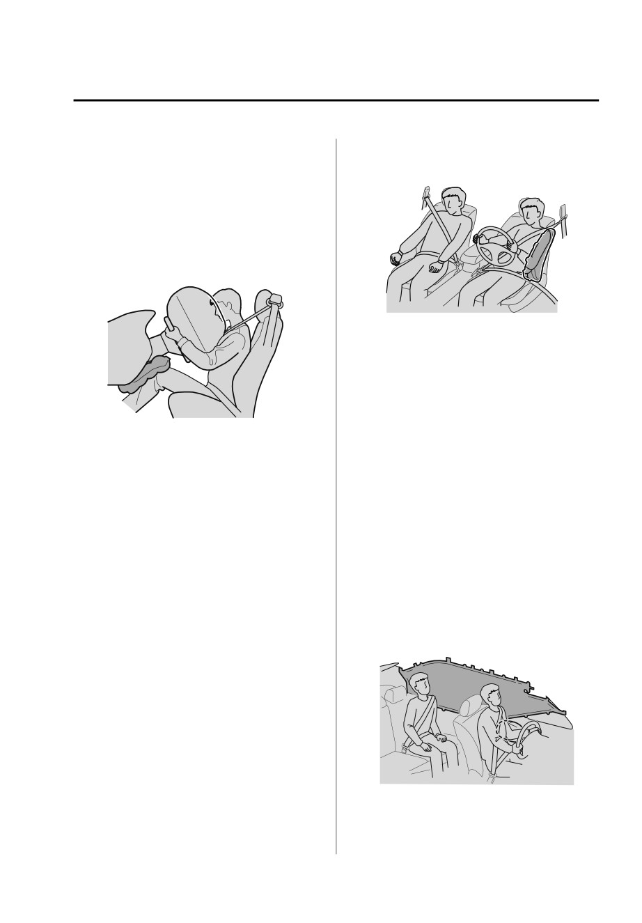
▼ Driver and Front Passenger Knee
deployment, refer to "SRS Air Bag
Air Bags
Deployment Criteria" (page 2-61).
The knee air bags are equipped under
The driver's dual-stage air bag controls
air bag inflation in two energy stages.
the instrument panel.
During an impact of moderate severity,
2-58
Essential Safety Equipment
SRS Air Bags
If the air bag crash sensors receive a
passenger occupant classification
frontal impact of greater than
system (page 2-64).
moderate force, the knee air bags
deploy immediately to reduce impact
to the driver and front passenger's
legs.
For more details about air bag
deployment, refer to "SRS Air Bag
Deployment Criteria" (page 2-61).
▼ Curtain Air Bags
The curtain air bags are mounted in the
front and rear window pillars, and the
roof edge along both sides.
When the air bag crash sensors detect
a side impact of greater than moderate
force, the curtain air bag inflates
▼ Side Air Bags
quickly and helps to reduce injury
mainly to the driver and front and rear
The side air bags are mounted in the
outboard passengers' heads caused by
outboard sides of the front seatbacks.
directly hitting interior parts such as a
When the air bag crash sensors detect
door or window.
a side impact of greater than moderate
For more details about air bag
force, the system inflates the side air
deployment, refer to "SRS Air Bag
bag only on the side in which the
Deployment Criteria" (page 2-61).
vehicle was hit. The side air bag inflates
In a side impact:
quickly to reduce injury to the driver or
Greater than moderate impact to one
front passenger's chest caused by
side of the vehicle will cause the
directly hitting interior parts such as a
curtain air bag on that side only to
door or window.
inflate.
For more details about air bag
deployment, refer to "SRS Air Bag
Deployment Criteria" (page 2-61).
In addition, the front passenger side air
bag is designed to only deploy in
accordance with the total seated
weight on the front passenger seat. For
details, refer to the driver and front
Only one side curtain air bag will
deploy on the side of the vehicle that
receives the force of an impact.
2-59
Essential Safety Equipment
SRS Air Bags
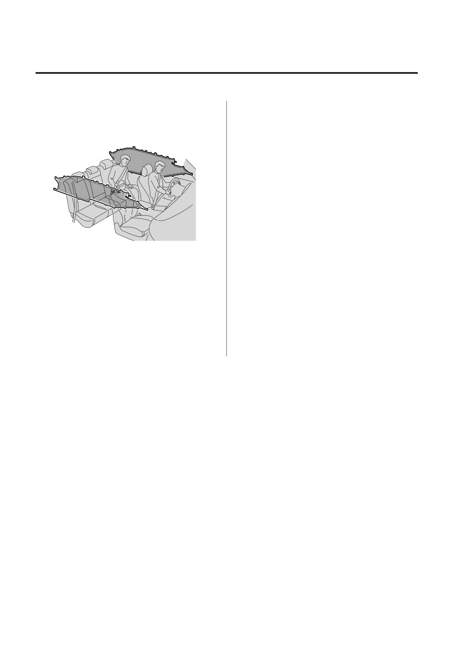
In a roll-over:
In response to a vehicle roll-over, both
curtain air bags inflate.
Both curtain air bags will deploy after
the roll-over accident is detected.
▼ Warning Light/Beep
A system malfunction or operation
conditions are indicated by a warning.
Refer to Air Bag/Front Seat Belt
Pretensioner System Warning
Indication/Warning Light on page
7-27.
2-60
Essential Safety Equipment
SRS Air Bags
SRS Air Bag Deployment Criteria
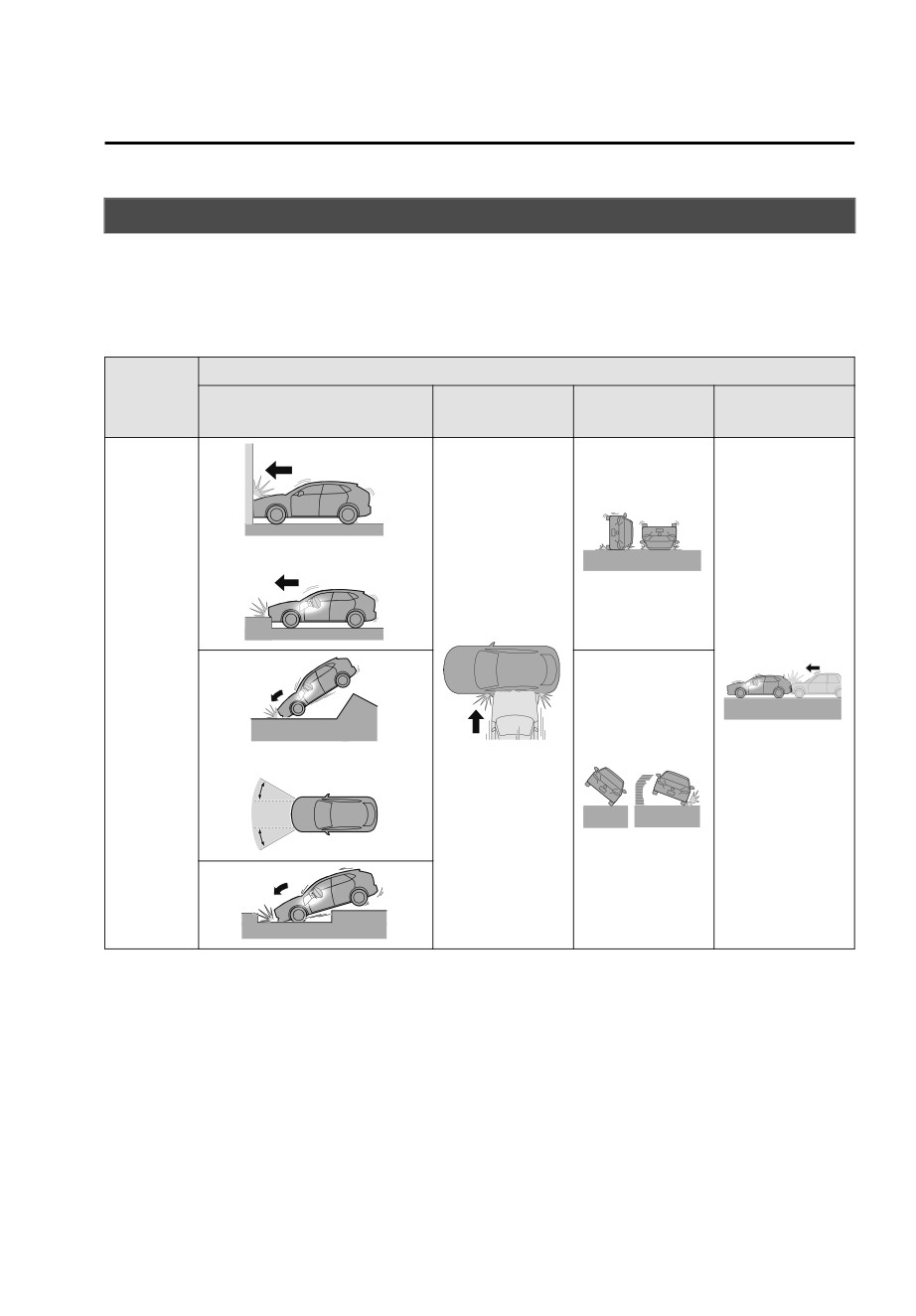
▼ SRS Air Bag Deployment Criteria
This chart indicates the applicable SRS equipment that will deploy depending on the
type of collision.
(The illustrations are the representative cases of collisions.)
Types of collision
SRS equip-
A severe frontal/near frontal
A severe side col-
A roll-over/near
ment
A rear collision
collision
lision
roll-over*2
2-61

Essential Safety Equipment
SRS Air Bags
Types of collision
SRS equip-
A severe frontal/near frontal
A severe side col-
A roll-over/near
ment
A rear collision
collision
lision
roll-over*2
Front seat
belt preten-
X*1
X*1
X*1
sioner
Driver air
X
―
―
bag
No air bag and
Front pas-
front seat belt
senger air
X*1
―
―
pretensioner will
bag
be activated in a
Knee air
X*1
―
―
rear collision.
bag
X*1 (impact side
Side air bag
―
―
only)
Curtain air
X (impact side
―
X (both sides)
bag
only)
X: The SRS air bag equipment deploys in a collision.
―:The SRS air bag equipment does not deploy in a collision.
*1
The front passenger front and side air bags, seat belt pretensioner and knee air bag are designed to
deploy depending on the condition of the total seated weight on the front passenger seat.
*2
In a roll-over accident, the seat belt pretensioners and the curtain air bags deploy.
NOTE
In a frontal offset collision, the equipped air bags and pretensioners may all deploy
depending on the direction, angle, and rate of impact.
2-62
Essential Safety Equipment
SRS Air Bags
enough to deploy the SRS air bag
Limitations to SRS Air Bag
equipment.
▼ Limitations to SRS Air Bag
Impacts involving trees or poles
In severe collisions such as those
described previously in "SRS Air Bag
Deployment Criteria", the applicable
SRS air bag equipment will deploy.
However, in some accidents, the
equipment may not deploy depending
on the type of collision and its severity.
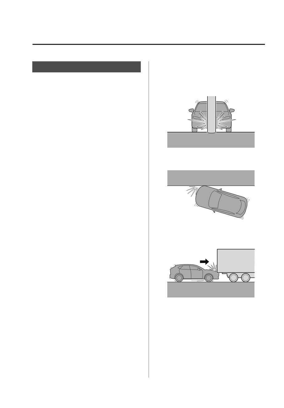
Limitations to front/near front
collision detection:
Frontal offset impact to the vehicle
The following illustrations are
examples of front/near front collisions
that may not be detected as severe
Rear-ending or running under a
truck's tail gate
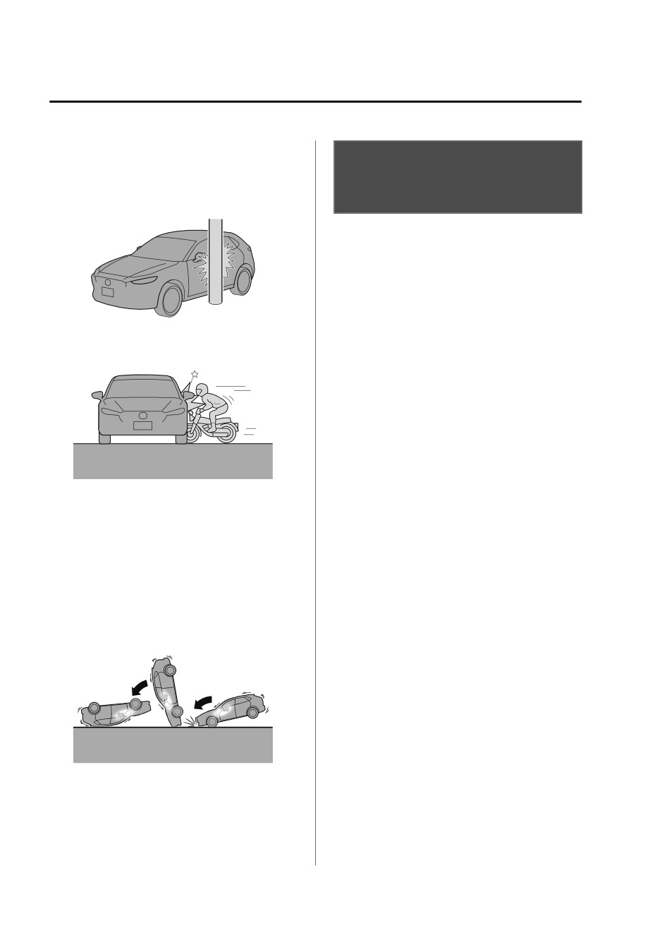
Limitations to side collision detection:
The following illustrations are
examples of side collisions that may
2-63
Essential Safety Equipment
SRS Air Bags
not be detected as severe enough to
Driver and Front
deploy the SRS air bag equipment.
Passenger Occupant
Side impacts involving trees or poles
Classification System
▼ Driver and Front Passenger
Occupant Classification System
First, please read "Supplemental
Restraint System (SRS) Precautions"
(page 2-52) carefully.
▼ Driver Seat Slide Position Sensor
Side impacts with two-wheeled
vehicles
Your vehicle is equipped with a driver
seat slide position sensor as a part of
the supplemental restraint system. The
sensor is located under the driver seat.
The sensor determines whether the
driver seat is fore or aft of a reference
position and sends the seat position to
the diagnostic module (SAS unit).
The SAS unit is designed to control the
deployment of the driver air bag
Limitations to roll-over detection:
depending on how close the driver
The following illustration is an example
seat is to the steering wheel.
of an accident that may not be
The air bag/front seat belt
detected as a roll-over accident.
pretensioner system warning light
Therefore, the front seat belt
flashes if the sensor has a possible
pretensioners and curtain air bags may
malfunction (page 2-60).
not deploy.
▼ Front Passenger Seat Weight
Sensors
Pitch end over end
Your vehicle is equipped with a front
passenger seat weight sensors as a part
of the supplemental restraint system.
These sensors are located under both
of the front passenger seat rails. These
sensors determine the total seated
weight on the front passenger seat and
monitor the seat belt buckle for the
front passenger seat. The SAS unit is
designed to prevent the front
passenger front and side air bags and
knee air bags, and seat belt
pretensioner system from deploying if
2-64
Essential Safety Equipment
SRS Air Bags
the front passenger air bag
bags, and seat belt pretensioners will
deactivation indicator light illuminates.
not deploy during a collision.
To reduce the chance of injuries
caused by deployment of the front
passenger air bag, the system
deactivates the front passenger front
and side air bags and knee air bags,
and also the seat belt pretensioner
system when the front passenger air
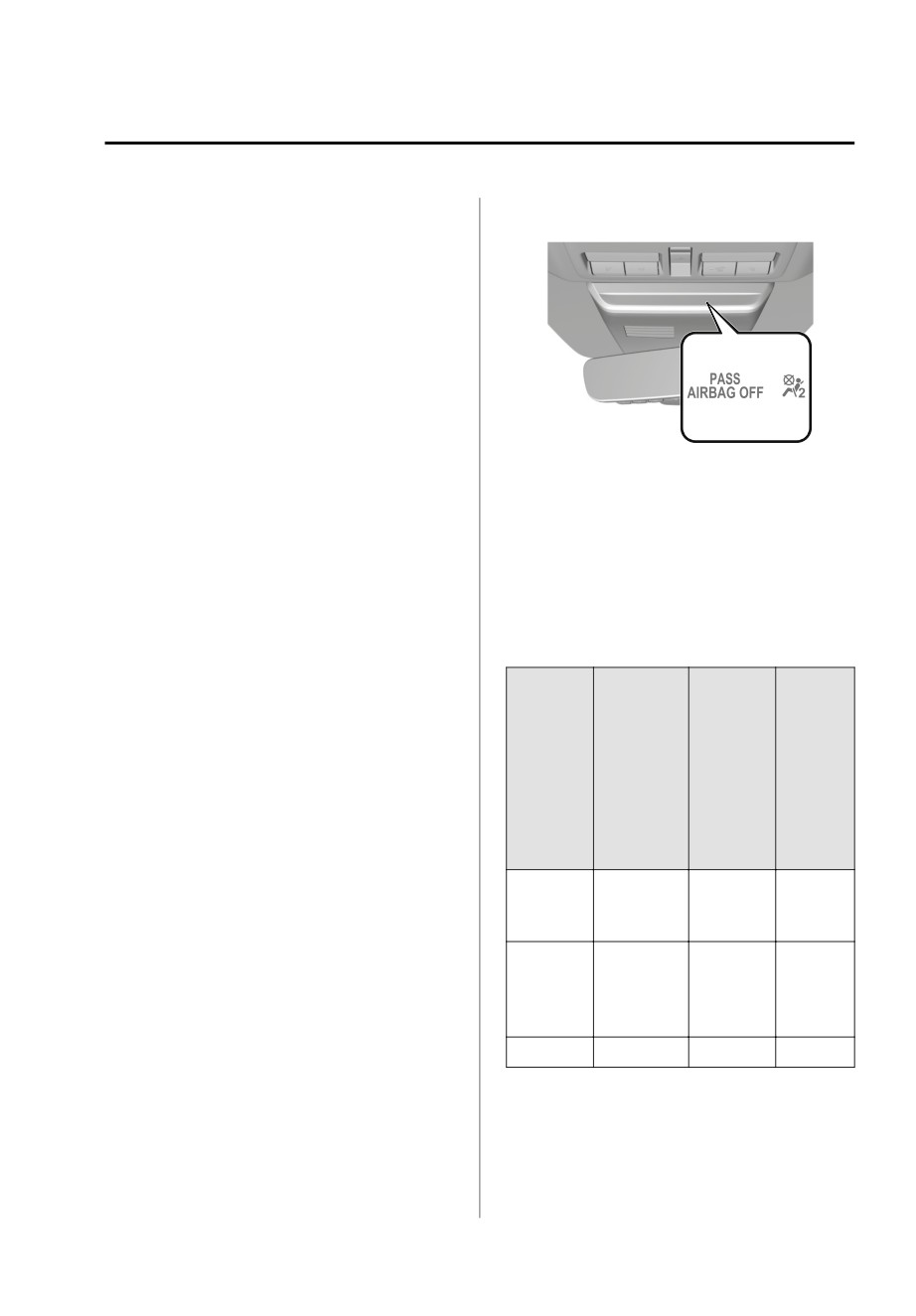
bag deactivation indicator light
illuminates. Refer to the following
table for the front passenger air bag
If the front passenger weight sensors
deactivation indicator light
are normal, the indicator light
illumination conditions.
illuminates when the power switch is
switched ON. The light turns off after a
This system shuts off the front
few seconds. Then, the indicator light
passenger front and side air bags and
illuminates or is off under the following
knee air bags, and seat belt
conditions:
pretensioner system, so make sure the
front passenger air bag deactivation
Front passenger air bag deactivation
indicator light illuminates according to
indicator light on/off condition chart
the following table.
Condition
The air bag/front seat belt
detected
Front pas-
Front
by the
Front pas-
pretensioner system warning light
senger
passen-
front pas-
senger air
flashes and the front passenger air bag
front and
ger seat
senger oc-
bag deacti-
deactivation indicator light illuminates
side and
belt pre-
cupant
vation indi-
if the sensors have a possible
knee air
tensioner
classifica-
cator light
malfunction. If this happens, the front
bags
system
tion sys-
passenger front and side air bags and
tem
knee air bags, and seat belt
pretensioner system will not deploy.
Empty
Deactivat-
Deacti-
(Not occu-
On
Front passenger air bag deactivation
ed
vated
pied)
indicator light
Child or
This indicator light illuminates to
child-re-
Deactivat-
Deacti-
remind you that the front passenger
On
straint sys-
ed
vated
front and side air bags and knee air
tem*1
Adult*2
Off
Ready
Ready
*1
If a larger child sits on the front passenger
seat, the sensors might detect the child as
being an adult depending on the child's
physique.
*2
If a smaller adult sits on the front passenger
seat, the sensors might detect the person as
2-65
Essential Safety Equipment
SRS Air Bags
being a child depending on the person's
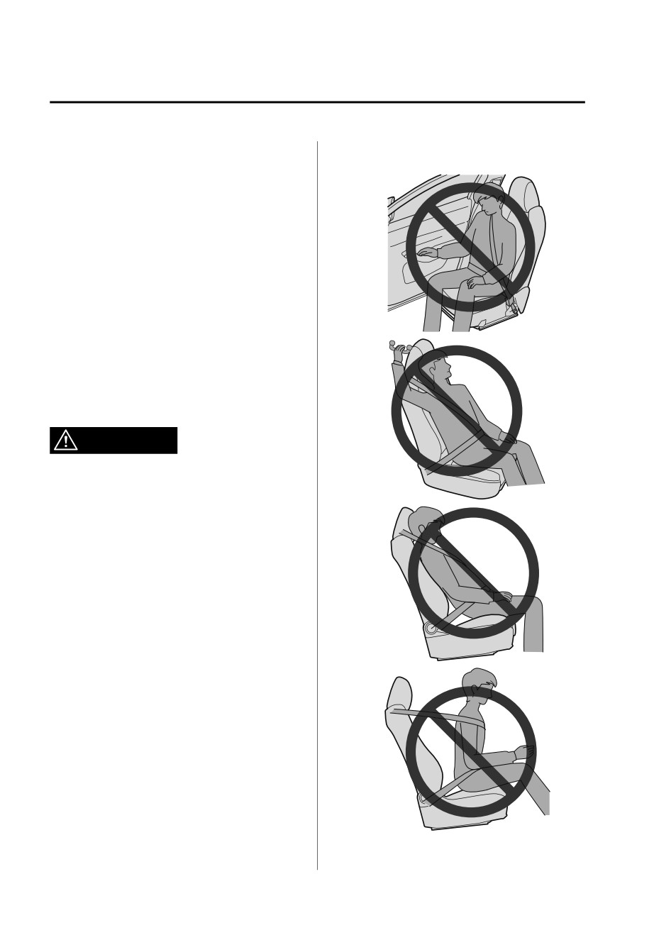
¾ A front passenger is seated as shown
physique.
in the following figure:
The curtain air bag is ready for inflating
regardless of what the front passenger air bag
deactivation indicator light on/off condition
chart indicates.
If the front passenger air bag
deactivation indicator light does not
illuminate when the power switch is
switched ON and does not illuminate
as indicated in the front passenger air
bag deactivation indicator light on/off
condition chart, do not allow a child to
sit in the front passenger seat and
consult an Authorized Mazda Dealer
as soon as possible. The system may
not work properly in an accident.
WARNING
Do not decrease the total seated
weight on the front passenger seat:
When an adult or large child sits on the
front passenger seat, decreasing the
total seated weight on the front
passenger seat required for air bag
deployment is dangerous. The front
passenger seat weight sensors will
detect the reduced total seated weight
condition and the front passenger front
and side air bags and knee air bags,
and the seat belt pretensioner system
will not deploy during an accident. The
front passenger will not have the
supplementary protection of the air
bag, which could result in serious
injury. Decreasing the total seated
weight on the front passenger seat
could result in an air bag not deploying
under the following conditions, for
example:
¾ A rear passenger pushes up on the
front passenger seat with their feet.
2-66
Essential Safety Equipment
SRS Air Bags
¾ Luggage or other items placed under
¾ A rear passenger or luggage push or
the front passenger seat or between
pull down on the front passenger
the front passenger seat and driver
seatback.
seat that push up the front passenger
¾ A rear passenger steps on the front
seat bottom.
passenger seat rails with their feet.
¾ Any accessories which might
¾ Luggage or other items are placed on
decrease the total seated weight on
the seatback or hung on the head
the front passenger seat are attached
restraint.
to the front passenger seat.
¾ Heavy items are placed in the
The front passenger front and side air
seatback map pocket.
bags and knee air bags, and the seat
¾ The seat is washed.
belt pretensioner system will
¾ Liquids are spilled on the seat.
deactivate if the front passenger air
¾ The front passenger seat is moved
bag deactivation indicator light
backward, pushing into luggage or
illuminates.
other items placed behind it.
¾ The front passenger seatback
contacts the rear seat.
¾ Luggage or other items are placed
Do not increase the total seated
between the front passenger seat
weight on the front passenger seat:
and driver seat.
When an infant or small child sits on
¾ Any accessories which might increase
the front passenger seat, increasing the
the total seated weight on the front
total seated weight on the front
passenger seat are attached to the
passenger seat is dangerous. The front
front passenger seat.
passenger seat weight sensors will
detect the increased total seated
weight, which could result in the
CAUTION
unexpected deployment of the front
passenger front and side air bags and
¾ To assure proper deployment of the
knee air bags, and seat belt
front air bag and to prevent damage
pretensioner system in an accident and
to the sensors in the front seat
may cause serious injury. Increasing the
bottoms:
total seated weight on the front
¾ Do not place sharp objects on the
passenger seat could result in the front
front seat bottoms or leave heavy
passenger front and side air bags and
luggage on them.
knee air bags, and seat belt
¾ Do not spill any liquids on the
pretensioner system deployment in an
front seats or under the front seats.
accident under the following
conditions, for example:
¾ To allow the sensors to function
properly, always perform the
¾ Luggage or other items are placed on
following:
the seat with the child in the
child-restraint system.
¾ Adjust the front seats as far back as
¾ The front passenger seat contacts the
possible and always sit upright
vehicle ceiling.
against the seatbacks with seat
belts worn properly.
2-67
Essential Safety Equipment
SRS Air Bags
¾ If you place your child on the front
If the front passenger air bag
passenger seat, secure the
deactivation indicator light
child-restraint system properly and
illuminates when an adult is seated
slide the front passenger seat as far
in the front passenger seat, have the
back as possible (page 2-44).
passenger re-adjust their posture by
sitting with their feet on the floor,
NOTE
and then re-fastening the seat belt. If
the front passenger air bag
The system requires about 10
deactivation indicator light still
seconds to alternate between turning
illuminates, move the passenger to
the front passenger front and side air
the rear seat. If sitting in the rear seat
bags and knee air bags, and seat belt
is not possible, slide the front
pretensioner system on or off.
passenger seat as far back as
The front passenger air bag
possible. Consult an Authorized
deactivation indicator light may
Mazda Dealer as soon as possible.
illuminate repeatedly if luggage or
other items are put on the front
▼ Driver and Front Passenger Buckle
passenger seat, or if the temperature
Switches
of the vehicle's interior changes
The buckle switches on the front seat
suddenly.
belts detect whether or not the front
The front passenger air bag
seat belts are securely fastened and
deactivation indicator light may
further control the deployment of the
illuminate for 10 seconds if the total
air bags.
seated weight on the front passenger
seat changes.
The air bag/front seat belt
pretensioner system warning light
might illuminate if the front
passenger seat receives a severe
impact.
If the front passenger air bag
deactivation indicator light does not
illuminate after installing a
child-restraint system on the front
passenger seat, first, re-install your
child-restraint system according to
the procedure in this owner's
manual. Then, if the front passenger
air bag deactivation indicator light
still does not illuminate, install the
child-restraint system on the rear seat
and consult an Authorized Mazda
Dealer as soon as possible.
2-68
Essential Safety Equipment
SRS Air Bags
Constant Monitoring
▼ Constant Monitoring
The following components of the air
bag systems are monitored by a
diagnostic system:
Front air bag sensors
Crash sensors, and diagnostic
module (SAS unit)
Side crash sensors
Air bag modules
Front seat belt pretensioners
Air bag/Front seat belt pretensioner
system warning light
Related wiring
Driver seat slide position sensor
Front passenger occupant
classification sensor
Front passenger occupant
classification module
Front passenger air bag deactivation
indicator light
Front passenger seat belt buckle
switch
The diagnostic module continuously
monitors the system's readiness. This
begins when the power switch is
switched ON and continues while the
vehicle is being driven.
2-69
Before Driving
3
Use of various features, including keys, doors, mirrors and
windows.
Electric Vehicles
3-2
Windows
3-49
Electric Vehicles
3-2
Power Windows
3-49
Charging
3-10
Moonroof*
3-51
Keys
3-25
Security System
3-54
Keys
3-25
Modification and Add-
Keyless Entry System
3-27
On Equipment
3-54
Immobilizer System
3-54
Advanced Keyless Entry
System
3-31
Driving Tips
3-56
Advanced Keyless Entry
Break-In Period
3-56
System*
3-31
Hazardous Driving
3-56
Operational Range
3-32
Floor Mat
3-57
Rocking the Vehicle
3-57
Winter Driving
3-58
Doors and Locks
3-33
Overloading
3-59
Door Locks
3-33
Driving on Uneven Road
3-60
Liftgate
3-41
Towing
3-61
Mirrors
3-44
Trailer Towing
3-61
Mirrors
3-44
Recreational Towing
3-61
*Some models.
3-1
Before Driving
Electric Vehicles
Electric Vehicles
▼ Electric Vehicles
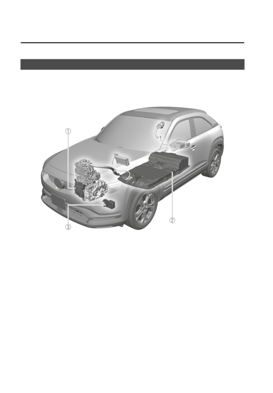
Electric vehicles are driven by motor power using the electrical power stored in the
high voltage battery. This vehicle is an eco-friendly vehicle which emits no exhaust
gas because fuel is not used.
1. Motor, Regenerative braking
2. High voltage battery
3. Approaching vehicle audible system
Motor
The motor transmits the motor power to the wheels using the electrical power of the
high voltage battery.
Regenerative braking
Regenerative braking uses the motor to decelerate the vehicle. Power is generated
by the wheels rotating the motor while decelerating and the generated power
charges the high voltage battery.
Refer to Steering Wheel Paddle on page 3-7.
High voltage battery
The high voltage battery is a large-capacity battery and stores the charged power and
the electrical power generated by regenerative braking.
3-2
Before Driving
Electric Vehicles
Approaching vehicle audible system
The approaching vehicle audible system notifies pedestrians of the vehicle
approaching using a warning sound while driving at low speeds.
Refer to Approaching Vehicle Audible System on page 3-9.
▼ Cautions on Use
An electric vehicle has high voltage areas and high temperature areas.
Labels indicating the cautions on use are applied to these areas. Always follow the
instructions on the label and use the vehicle correctly.
WARNING
Be very careful of high voltage areas. In addition, do not disassemble, modify, or
remove any high voltage parts:
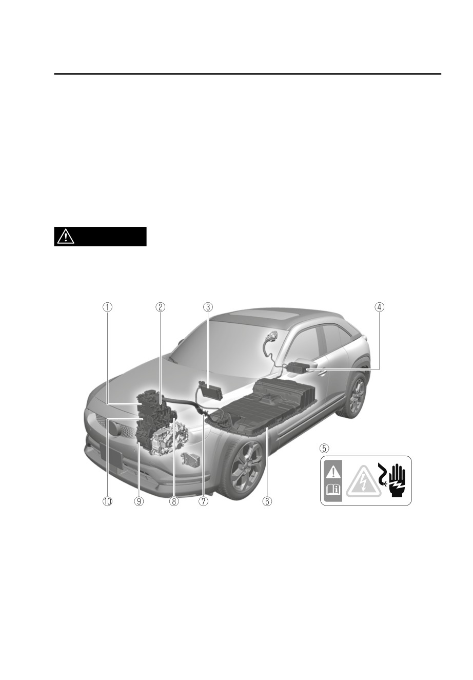
The following areas contain high voltage parts and may cause electrical shock if
touched.
1. DC-DC Converter
2. Junction Box
3. PTC Heater
4. Onboard Charger
5. Warning Label Example
6. High Voltage Battery
7. High Voltage Cable
8. Electric Compressor
9. Motor
3-3
Before Driving
Electric Vehicles
10.Inverter
Be very careful of high temperature areas:
Always follow the instructions on the labels inside the motor compartment. After
driving, the motor temperature may be high.
Do not open the hood while the EV system or Climate Control Timer is operating
or during timer charging, normal charging, or quick charging:
The cooling fan in the motor compartment may rotate suddenly and your hand,
clothes, or accessories may touch the fan or become caught, resulting in serious
injury or death.
▼ Maintenance and Repairs
¾ If the high voltage battery is used on
a vehicle other than one equipped
For vehicle maintenance or repairs,
(including modified vehicles) with a
consult an Authorized Mazda Dealer.
high voltage battery, an electrical
Technical knowledge and skill are
shock accident, heat generation,
necessary in handling the high voltage
smoking, combustion, and
battery.
explosions, or an electrolyte leakage
may occur.
WARNING
Heed the following instructions to
To ensure safe and correct handling of
prevent deterioration of the high
the high voltage battery, always heed
voltage battery or damage to the high
the following precautions:
voltage battery.
¾ Do not remove the high voltage
Do not leave the vehicle for a long
battery.
time under extremely high or low
¾ Do not resell, transfer, or modify the
temperature conditions.
high voltage battery.
Do not leave the vehicle for 14 days
¾ Do not use the battery on vehicles
or longer while the high voltage
other than those equipped with the
battery is at 0 (zero) charge.
high voltage battery.
NOTE
If the high voltage battery is not
The high voltage battery has a certain
battery life. The battery life differs
handled properly, the following may
occur which could lead to serious
depending on how the vehicle is used
and the driving conditions.
injury or death:
¾ Touching an unattended high voltage
▼ Scrapping Your Vehicle and
battery may cause an electrical shock
Disposing of the High Voltage
accident.
Battery
The high voltage battery is collected to
prevent accidents involving it. When
scrapping your vehicle or replacing the
high voltage battery, consult
Authorized Mazda Dealer. Please
3-4

Before Driving
Electric Vehicles
cooperate in ensuring that the vehicle's
Never approach objects that are on
high voltage battery is collected.
fire or extremely hot:
Electrolyte in the high voltage battery
WARNING
may cause a fire.
If the vehicle catches fire, extinguish
Appropriate disposal of the high
the fire using a fire extinguisher (type
voltage battery:
ABC, BC, or C).
If the high voltage battery is not
Only extinguish a fire with water when
collected and disposed of
a large amount of water is available
appropriately, such as by leaving it
such as from a fire hydrant. Otherwise,
unattended or illegally abandoning it,
it could lead to an accident.
some other person may touch it which
▼ Advice for Using Electric Vehicles
could cause an electrical shock
accident leading to serious injury.
Unique sound and vibration occurring
with electric vehicles
▼ Accident Occurs
Electric vehicles have a unique sound
If the vehicle receives an impact of a
and vibration which differ from
certain level or greater in a collision,
non-electric vehicles. The following
the EV system stops. In this case, the
sounds or vibration may occur,
EV system malfunction warning
however, this is unique to electric
indication/warning light displays/turns
vehicles and it does not indicate a
on and the EV system may not start.
problem.
Contact an Authorized Mazda Dealer
immediately.
Motor operation sound.
Operation sound of coolant pump
WARNING
and cooling fan while charging.
Operation sound of regenerative
Never touch electrical wiring that may
braking.
be protruding into or outside of the
Relay operation sound when EV
cabin:
system is started or stopped.
Otherwise, it could result in electrical
Brake system operation sound and
shock and serious injury.
vibration.
Operation sound of brake system
Never touch any area where
Sound can be heard from the front of
electrolyte is visible or electrolyte is
the vehicle under the following
leaking from the area:
conditions:
If any electrolyte from the high voltage
The driver's door is opened.
battery gets in the eyes or on the skin,
The power switch is switched ON.
it could cause loss of vision or skin
The brake pedal is operated.
reactions. In the unlikely event that
The brake system operates
electrolyte comes into contact with the
automatically.
eyes or skin, flush with large quantities
Several minutes have passed since
of water immediately and seek
the EV system was stopped.
immediate medical attention.
Vibration of brake pedal
3-5
Before Driving
Electric Vehicles
Vibration of the brake pedal might
perform smooth starts,
be felt under the following
acceleration, and deceleration.
conditions:
Try to drive maintaining a constant
speed and avoid speeding.
The power switch is switched ON.
Inspect the tire pressures regularly
The brake pedal is operated.
and always adjust the tire pressures
to the specified inflation pressure.
By maintaining a sufficient distance
High voltage battery level and
between vehicles and using the
temperature
regenerative braking well, more
If the high voltage battery level is low
electrical power can be charged to
or the high voltage battery temperature
the high voltage battery.
is low, the vehicle speed may not
increase even if the accelerator pedal is
depressed because the motor output is
Pointers for Maintaining Long Battery
restricted. Drive the vehicle following
Life
the instructions displayed on the
The high voltage battery life changes
multi-information display.
depending on the vehicle conditions or
charging method.
To Extend Cruising Distance
For maintaining a long high voltage
battery life, be careful of the following:
The electrical power consumption
Charging the high voltage battery
while driving can be reduced and the
cruising distance can be extended by
Avoid unnecessary, frequent
doing the following operations.
charging.
Charge the battery normally and
With the charging connector
avoid quick charging as much as
connected, turn on the climate
possible.
control system to provide a
Only charge the battery with as much
comfortable temperature in the
power as needed, and do not always
cabin before driving.
fully charge the battery. The
When driving during cold
maximum charge limit can be set.
temperatures, use the seat warmer
Refer to Charging Settings on page
or steering warmer instead of the
3-21.
climate control system.
Adjust the climate control system
Parking the vehicle
to a moderate airflow and
Do not park the vehicle in a place
temperature setting.
where the ambient temperature is
Refrain from using the defogger
extremely high or low.
under conditions other than when
Do not leave the vehicle while the
a window is fogged or frozen.
remaining high voltage battery power
Unload unnecessary cargo to
is extremely low.
reduce the vehicle weight.
If the Excessive Battery Temperature
Avoid unnecessary sudden
notification is displayed on the
acceleration, rapid acceleration,
center display after driving the
and rapid deceleration. Instead,
vehicle, select Start.
3-6
Before Driving
Electric Vehicles
▼ Steering Wheel Paddle
The steering wheel paddle is a function that makes it easy to adjust the vehicle
speed according to the accelerator pedal operation.
Acceleration/deceleration is possible according to the various driving conditions
such as on an up or down slope, during traffic jams, or high-speed driving.
WARNING
Avoid using the steering wheel paddles when driving on wet roads, snow-covered
roads, or icy roads:
Otherwise, the tires will slip which could lead to an accident.
Setting
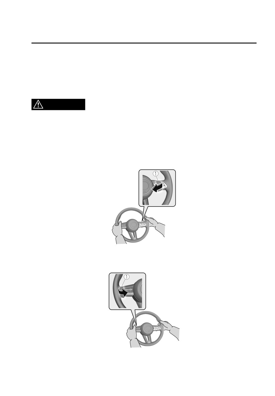
By operating the plus switch (+/OFF), the regenerative braking force is decreased
when releasing the accelerator pedal, and the vehicle accelerates quickly when
depressing the accelerator pedal.
1. Plus switch (+/OFF)
By operating the minus switch (-), the regenerative braking force is increased when
releasing the accelerator pedal, and the vehicle accelerates slowly when depressing
the accelerator pedal.
1. Minus switch (-)
3-7
Before Driving
Electric Vehicles
NOTE
When the cruise control and the Mazda Radar Cruise Control with Stop & Go
function (MRCC with Stop & Go function), or the Traffic Jam Assist (TJA) is
operating, the steering wheel paddle setting cannot be changed.
When performing the following operations, the steering wheel paddle returns to
the default setting.
Plus switch (+/OFF) is kept pulled for a certain period of time
Selector lever is shifted to any position from D
Power switch is switched OFF
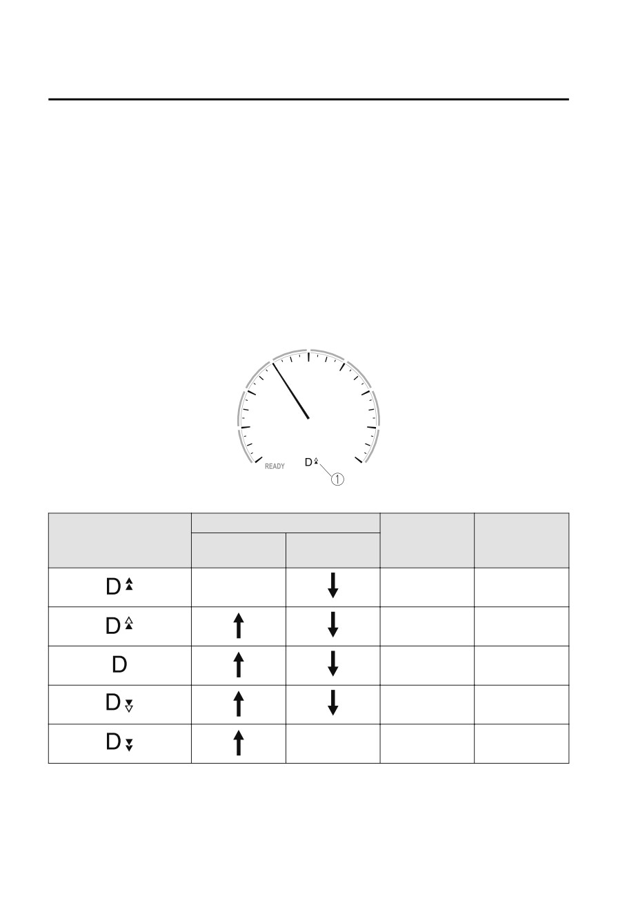
Indication
The operation condition of the steering wheel paddle is displayed on the
multi-information display.
1. Steering wheel paddle display
Switch operation
Regenerative
Indication
Plus switch (+/
Acceleration
Minus switch (-)
braking force
OFF)
-
Weak
Quickly
Slightly weak
Slightly quick
Normal
Normal
Slightly strong
Slightly slow
-
Strong
Slowly
3-8
Before Driving
Electric Vehicles
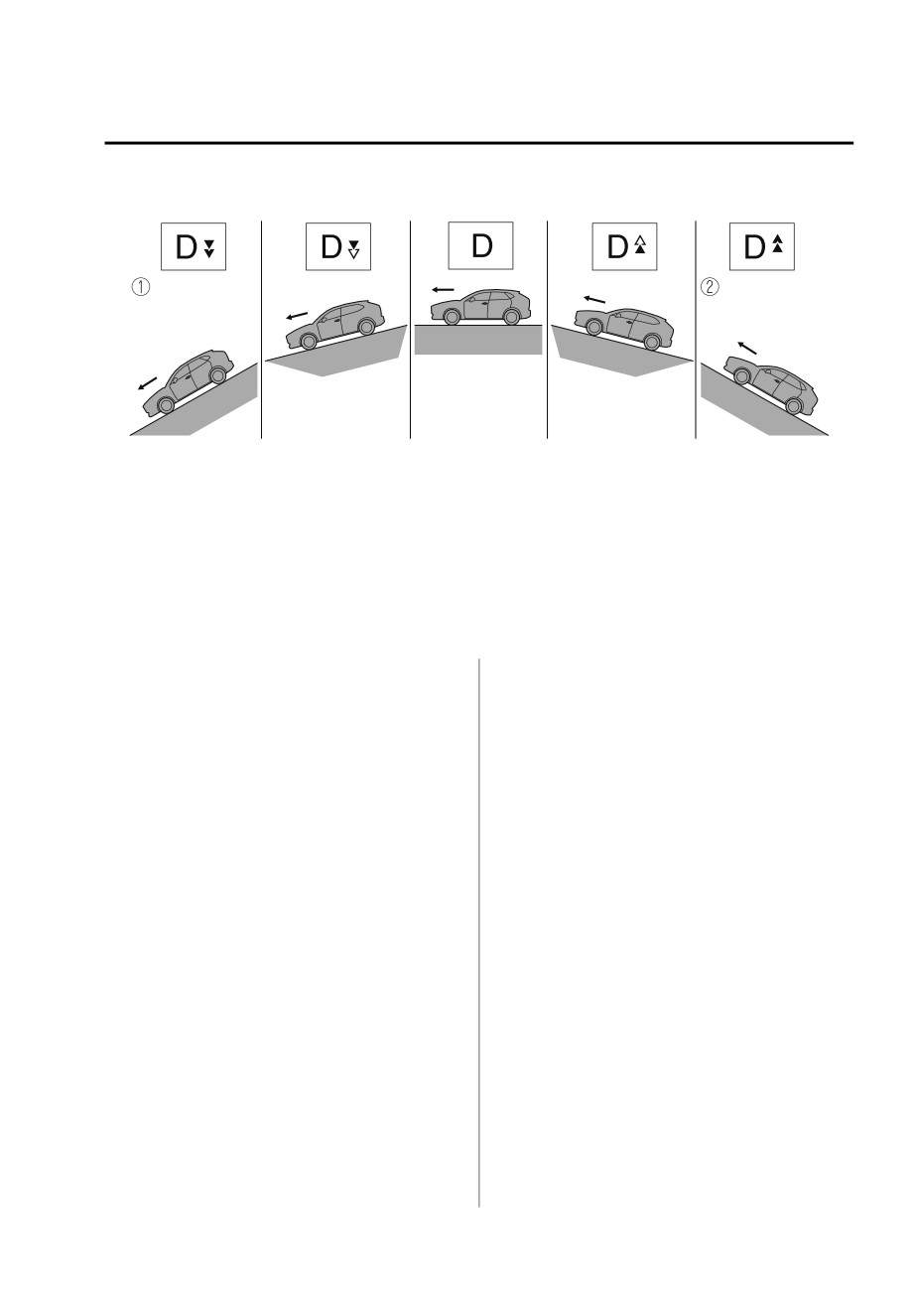
Particular driving situation
1. Driving on a downward slope or during traffic jams
2. Driving on an upward slope or expressways
NOTE
If the high voltage battery level is high or the high voltage battery temperature is
low, the indication on the multi-information display changes because regenerative
braking is restricted, however, there may be a small change in the regenerative
braking force or no change at all.
The brake lights may turn on when the regenerative braking force is strong.
▼ Approaching vehicle audible
The electronic sound operates when all
system
of the following conditions are met.
The approaching vehicle audible
The selector lever is in a position
system notifies pedestrians of the
other than N and P.
vehicle approaching using a warning
All the doors and the liftgate are
sound while driving at low speeds.
closed.
The approaching vehicle audible
Emergency braking is not being
system operates under the following
performed.
conditions.
The vehicle accelerates from a stop
and the vehicle speed is 30 km/h
(19 mph) or slower.
The vehicle decelerates and the
vehicle speed is 25 km/h (16 mph)
or slower.
You release your foot from the brake
pedal with the selector lever in a
position other than P.
▼ Electronic sound
Electronic sound is a system that uses a
speaker to emit sound into the cabin
to notify the driver of the vehicle's
behavior.
3-9

Before Driving
Electric Vehicles
Charging
▼ Cautions Concerning Charging
Otherwise, it could lead to an
electrical shock resulting in an
accident.
WARNING
¾ Do not charge the high voltage
For occupants who use any medical
battery outside if there is the
device such as an implanted-type
possibility of heavy rain, strong
heart pacer or defibrillator, ask a
winds, or lightning.
doctor or manufacturer of the device
¾ Remove water with a clean cloth if
about how the medical device may be
the charge connector or charge plug
affected by the charging operation:
is wet.
Otherwise, the operation of the
¾ Do not touch the charge port or
medical device could be affected
charge cable with wet hands.
resulting in an accident.
¾ If the outlet is covered with snow
while charging, turn off the power
For occupants who use any medical
such as turning off the breaker,
device such as an implanted-type
remove the snow, and then remove
heart pacer or defibrillator, do not
the charge plug.
enter the cabin including the luggage
compartment while charging:
Do not use the charge cable if it has
Otherwise, the operation of the
any of the following malfunctions:
medical device could be affected
Otherwise, it could lead to an
resulting in an accident.
electrical shock resulting in an
accident.
Do not disassemble or modify the
¾ The charge connector is rusted or
charge port and the charge cable:
corroded.
Otherwise, it could lead to an
¾ The charge connector is damaged or
electrical shock resulting in an
foreign matter penetrates the charge
accident.
connector.
Always heed the following when
Refer to the instruction manual
charging:
accompanying the charge cable and
Otherwise, it could lead to an
use the charge cable correctly:
electrical shock resulting in an
If you handle the charge cable
accident.
incorrectly, it could result in an
¾ Never allow children to charge the
unexpected accident.
high voltage battery.
¾ Do not charge the high voltage
Always heed the following when
battery while the vehicle is covered
using the charge cable:
with a car cover.
Otherwise, the charge cable could be
damaged resulting in an accident.
Always heed the following when
¾ Do not pull out or bend the charge
charging in the rain or snow:
cable excessively.
3-10
Before Driving
Electric Vehicles
¾ Do not step on the charge cable or
NOTE
drag it on the ground.
Normal charging and quick charging
¾ When inserting/pulling out the
cannot be performed at the same
charge connector and the charge
time.
plug, do not twist them excessively.
The navigation system and the
¾ Do not apply excessive force to the
climate control system can be used
connected charge connector such as
even while charging. However, the
by applying your weight.
charging time increases because
¾ Keep objects which generate intense
electrical power is consumed. In
heat (such as a heater or cigarette)
some cases, power consumption
away from the charge cable.
may exceed the charged amount and
¾ Do not apply organic solvents, acid
charging may not finish.
or alkaline agents to the charge
If a power outage occurs while
cable.
charging, remove the plug and the
charge connector and start charging
from the beginning again.
CAUTION
Make sure that no water has
¾ Do not connect the booster cable to
accumulated in the charge connector
the lead-acid battery or remove the
and the charge port before charging.
lead-acid battery while charging the
If any foreign matter enters the
high voltage battery. Otherwise, the
charge connector or the charge port,
vehicle or charging device could be
do not start charging and consult an
damaged.
Authorized Mazda Dealer.
¾ If the charge connector is removed
▼ Preparation Before Charging
after the charging is finished, close
the charge port cap immediately. If
This vehicle is driven by consuming the
the charging lid is closed with the
electrical power stored in the high
charge port cap open, water or
voltage battery. Therefore, it is
foreign matter may enter the charge
necessary to charge the high voltage
port causing a malfunction.
battery.
¾ Always make sure that the charge
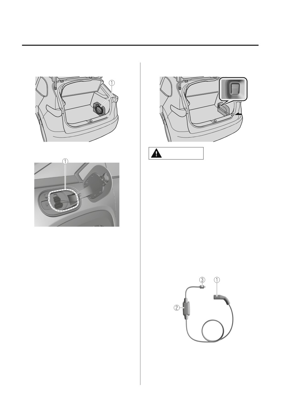
The parts related to charging are
cable is not connected to the vehicle
located in the following positions.
before driving. Because the vehicle
can be driven even while the charge
connector is not connected
completely, it could result in an
accident.
¾ If the charge port is frozen shut,
defrost the inlet using a hair dryer. If
the charge cable is inserted/pulled
out with the charge port frozen, it
could cause damage.
3-11
Before Driving
Electric Vehicles
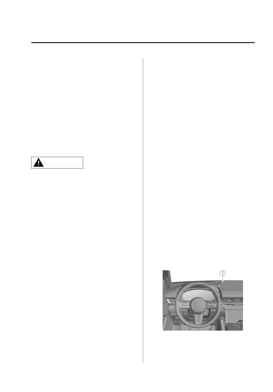
1. Mazda Connect
bag is facing toward the center of
the luggage compartment.
1. Charge cable
CAUTION
Be careful when handling the storage
bag because the hooks on the storage
bag have sharp areas. If your hands or
fingers touch the sharp areas, your
hands or fingers could be injured.
NOTE
When the storage bag hooks and the
luggage hooks hit against each other,
they make noise. If the noise distracts
1. Charge port
your attention while driving, wrap the
Charge cable
included sheet around the areas the
hooks make contact.
The charge cable is connected to the
power supply and the vehicle to send
electrical power to the vehicle. For
The component parts of the charge
details regarding the charge cable,
cable are as follows.
refer to the instruction manual
accompanying the charge cable.
In general, keep the charge cable at
home. If the charge cable is kept in the
vehicle, firmly secure it using the
following procedure.
1. Store the charge cable in its special
storage bag.
2. Attach the 2 hooks of the storage
bag to each of the 2 luggage hooks
on the right side of the luggage
1. Charge connector
compartment, and tightly secure
2. Control box
the storage bag. At this time, make
3. Charge plug
sure that the logo on the storage
3-12
Before Driving
Electric Vehicles
Charge connector
The component parts of the charge
port are as follows.
The charge connector is used for
connecting to the normal charge port.
When the charge connector is
connected to the normal charge port,
a vehicle system locks the charge
connector.
When the charge connector is locked
by the vehicle system, it unlocks when
the driver’s door is unlocked.
If the charge connector locked by the
vehicle system is not unlocked even
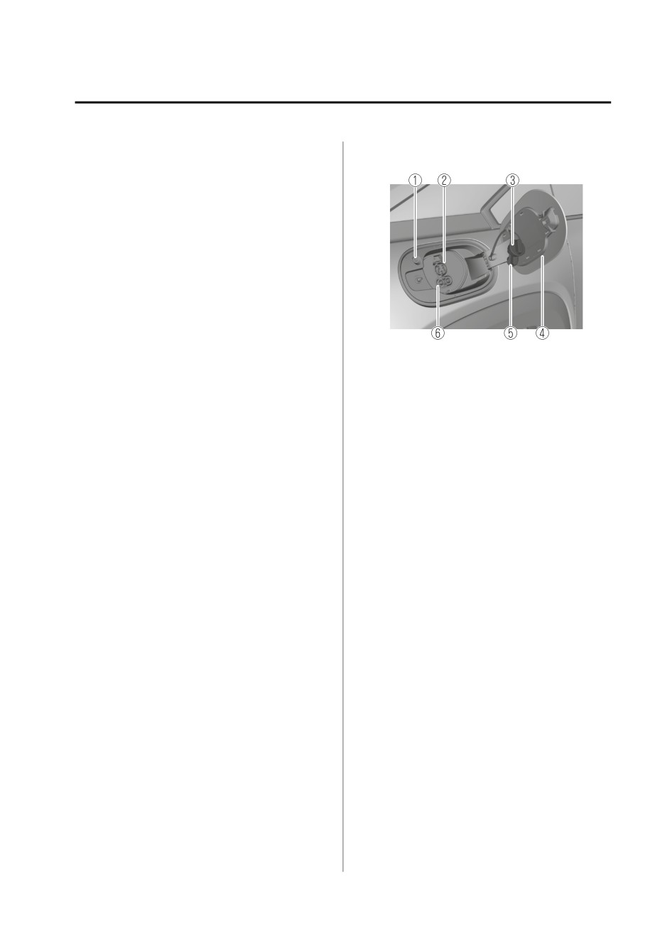
1. Charge indicator
though the driver’s door is unlocked,
2. Normal charge port
consult an Authorized Mazda Dealer.
3. Normal charge port cap
4. Charge lid
The conditions for locking the system
5. Quick charge port cap
on the vehicle side can be changed.
6. Quick charge port
For the procedure to change the
conditions, refer to Charging Settings
Charge indicator
on page 3-21.
The charging indicator indicates the
Control box
charging status by turning on/flashing
the light.
The control box indicates the charge
For the charging indicator
status by turning on/flashing the
illumination/flash pattern, refer to
indicator light.
Checking Charging Status on page
For the indicator light illumination/
3-18.
flash pattern, refer to the instruction
manual accompanying the charge
Normal charge port
cable.
The normal charge port is the part to
Charge plug
which the connector of the charge
cable is connected. This is used for
The charge plug is the part for
normal charging.
connecting to the power supply.
Charge lid
Charge port
The charge lid is locked/unlocked in
The charge port refers to the area
conjunction with the door locking/
where the charge connector is
unlocking mechanism.
connected.
When unlocking the driver’s door, the
charge lid is unlocked. When locking
the driver’s door, the charge lid is
locked.
However, if the driver’s door is
unlocked using the auxiliary key, the
charge lid is not unlocked.
3-13
Before Driving
Electric Vehicles
NOTE
If the vehicle is not used for a long
When the driver's door is locked using
period of time, we recommend that
any of the following functions, the
the battery heater is turned off using
charge lid is also locked at the same
[Settings] in Mazda Connect.
time.
When the battery heater operates,
the charging time could take longer.
Vehicle speed sensing auto door lock
function
Battery cooling
Auto re-lock function
If the high voltage battery temperature
Quick charge port
reaches 40 ℃ (104 ℉) or higher after
driving the vehicle, it is possible to cool
The quick charge port is the part to
the high voltage battery while the
which the connector of the quick
vehicle is parked for maintaining a long
charger is connected. This is used for
high voltage battery life.
quick charging.
If the Excessive Battery Temperature
Battery heater
notification is displayed on the center
display after completing a trip, select
The battery heater is designed to
Start to operate the battery cooling.
maintain the appropriate high voltage
battery temperature.
NOTE
Because the driving performance and
Because the electrical power of the
the charging performance decrease if
high voltage battery is used by the
the high voltage battery temperature
battery cooling, we recommend that
decreases, decreases in their
the charge connector is connected to
performance are reduced by
the vehicle while the battery cooling is
maintaining the appropriate high
operating, when parked in a location
voltage battery temperature using the
where charging is available.
battery heater.
▼ Charging
When the high voltage battery
temperature decreases significantly
Charging type
while parking or charging, the battery
There are two methods of charging the
heater operates. When the
high voltage battery, normal charging
temperature increases to the specified
and quick charging.
value, the heater turns off.
We recommend that you use normal
However, when the high voltage
charging as the preferred charging
battery level is low, the battery heater
method as this will help to keep the
does not operate.
high voltage battery in optimal
NOTE
condition and maintain a long battery
life.
Because the electrical power of the
high voltage battery is used by the
The exact charging time depends on
battery heater, we recommend that
various conditions at the time of
the charge connector is left
charging, such as the type of charger,
connected to the vehicle when
battery condition, charging patterns, as
parked in a location where charging
well as the battery temperature and
is available.
ambient temperature. In cold weather
3-14
Before Driving
Electric Vehicles
conditions, both the battery and
situations, this may lead to a significant
ambient temperature will affect the
increase in the charging time.
required charging time and, in certain
situations, this may lead to a significant
WARNING
increase in the charging time.
Always heed the following when
Normal charging
using a quick charger:
Normal Charging can be performed at
Otherwise, it could lead to an
home using either a household power
accident.
source such as a wall outlet or wall
¾ Do not use a charge cable which
box, or similar method (alternating
exceeds 30 m (98 ft).
current). Additionally, charging can be
¾ This vehicle is compatible with quick
performed at a public charging facility
chargers with charge cables of 30 m
using a charger other than a quick
(98 ft) or shorter and which do not
charger (direct current).
charge other devices or vehicles at
When charging is started after the
the same time.
remaining high voltage battery power
warning indication/warning light turns
on, the time it takes to fully charge the
How to perform normal charging
high voltage battery at a public AC
charging facility is about 5 hours. Using
1.
Shift the selector lever to the P
a household power source for charging
position.
will increase the charging time to fully
2.
Switch the power switch OFF.
charge the high voltage battery.
3.
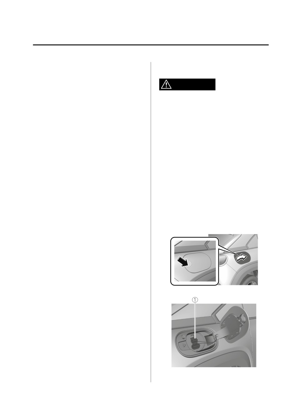
Press the location shown in the
For normal charging, the charging
figure to open the charge lid.
timer function can be used to charge
automatically from start to finish.
For details on how to use the charging
timer function, refer to Charging
Settings on page 3-21.
Quick charging
When charging is started at a quick
charging station (DC with 50 kW or
4.
Open the normal charge port cap.
higher) the high voltage battery can be
charged from a 20% to 80% battery
charge level in about 36 minutes. The
exact charging time depends on
various conditions at the time of
charging, such as the type of charger,
battery condition, charging patterns, as
well as the battery temperature and
ambient temperature. In cold weather
conditions, both the battery and
ambient temperature will affect the
required charging time and, in certain
1. Normal charge port cap
3-15
Before Driving
Electric Vehicles
5. Connect the charge plug to the
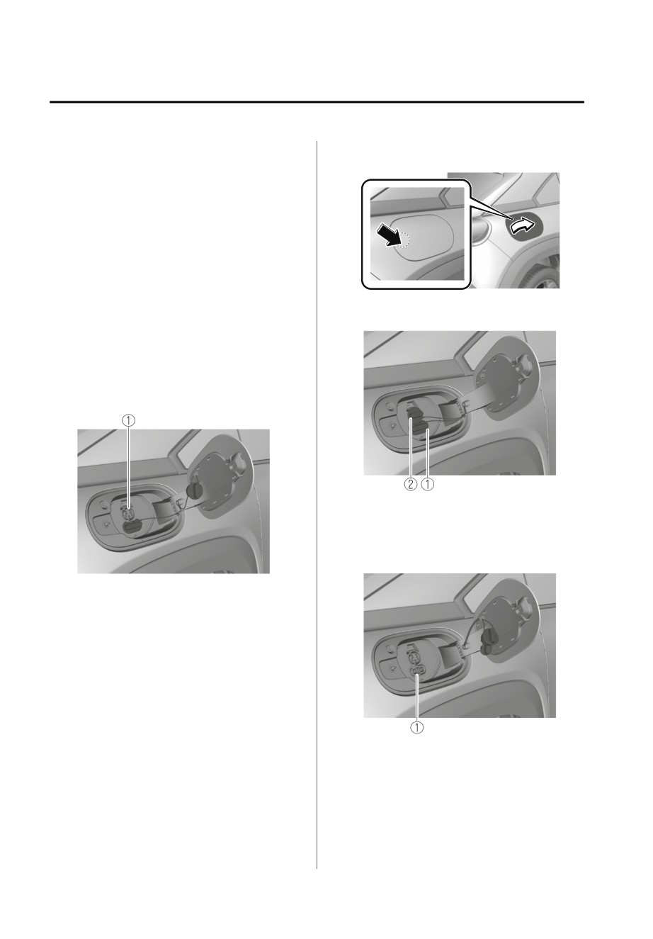
3. Press the location shown in the
outlet.
figure to open the charge lid.
6. Connect the charge connector to
the normal charge port. Charging
starts after connection is
completed.
Make sure to lock all the doors
before leaving the vehicle while
charging.
NOTE
4. Open the quick charge port cap
When the charging timer is set,
and normal charge port cap.
charging does not start even if the
charge connector is connected.
When you prefer to start charging
immediately, use the charging
timer cancellation function.
1. Quick charge port cap
2. Normal charge port cap
5. Connect the charge connector of
the quick charger to the quick
charge port.
1. Normal charge port
7. When charging is finished, remove
the charge connector.
8. Close the normal charge port cap.
9. Close the charge lid.
10.Remove the charge plug from the
power supply.
Make sure to lock all the doors before
leaving the vehicle.
How to perform quick charging
1. Quick charge port
6. Operate the quick charger to start
1. Shift the selector lever to the P
charging.
position.
2. Switch the power switch OFF.
3-16
Before Driving
Electric Vehicles
CAUTION
When operating a quick charger,
always use the charger according to
its instructions. If the quick charger
is operated incorrectly, the quick
charger or vehicle could be
damaged.
Make sure to lock all the doors
before leaving the vehicle while
charging.
7. When charging is finished, remove
the charge connector.
8. Close the quick charge port cap.
9. Close the charge lid.
Make sure to lock all the doors before
leaving the vehicle.
3-17
Before Driving
Electric Vehicles
▼ Checking Charging Status
Charge indicator
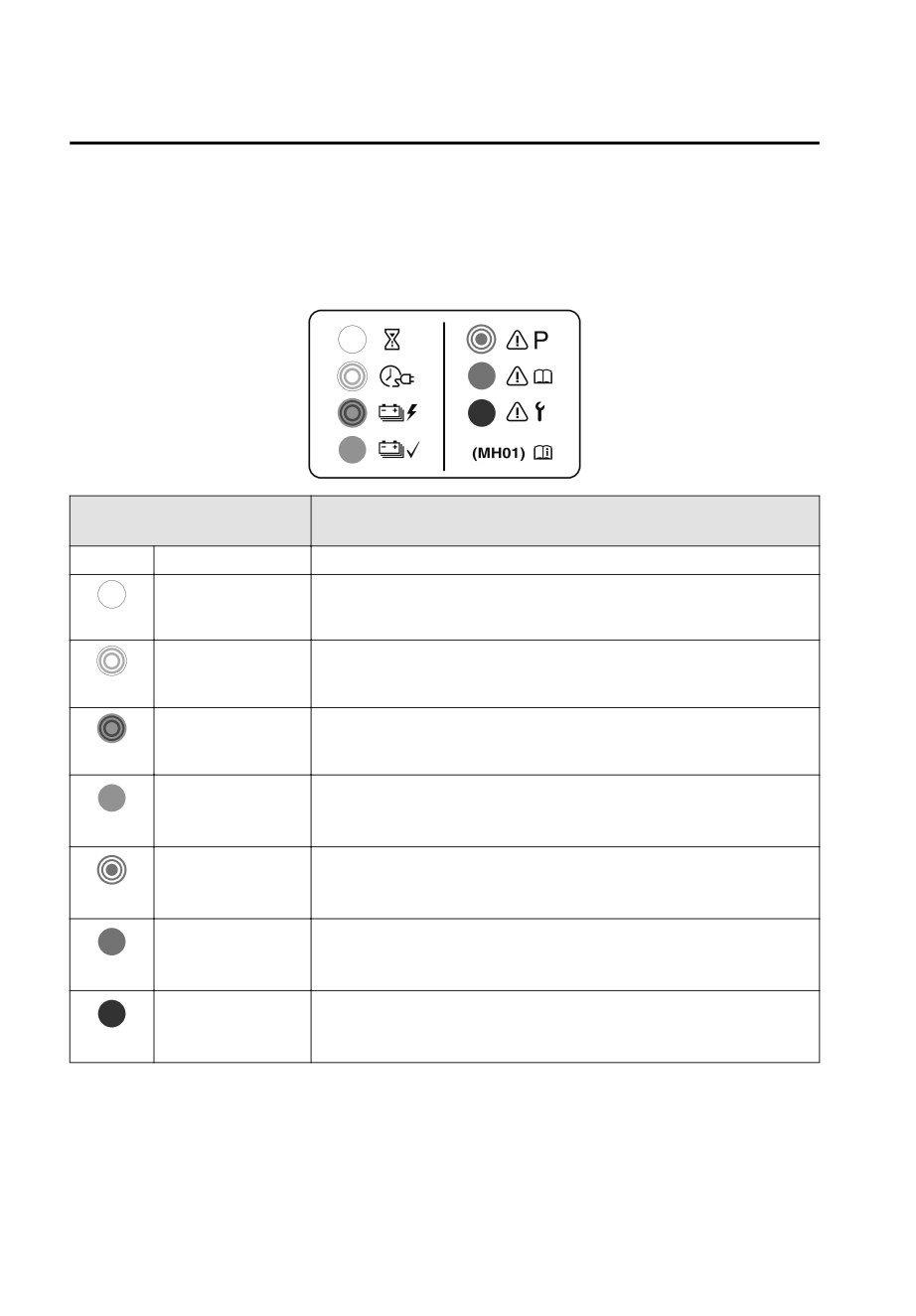
The illumination/flash pattern of the charge indicator can be checked using the
labels on the charge lid.
Charge indicator illumination/
Content
flash pattern
—
OFF
Charging is possible.
ON
Turns on when waiting for starting to charge.
(White)
Flashes slowly
The brightness changes when the charging timer is set.
(White)
Flashes slowly
The brightness changes during charging.
(Green)
Turns on when charging is completed.
ON
Turns off after a certain period of time has passed since charging was
(Green)
completed.
Flashes when the charging connector is connected and the selector
Flashes
lever is in a position other than P.
(Amber)
Shift the selector lever to the P position.
Turns on if there is a problem with the charging system when the
ON
charging connector is connected.
(Amber)
Wait a few minutes then reconnect the charging connector.
Turns on if there is a problem with the charging system and the
ON
charging port lid is opened or the charging connector is connected.
(Red)
Have your vehicle inspected by an Authorized Mazda Dealer.
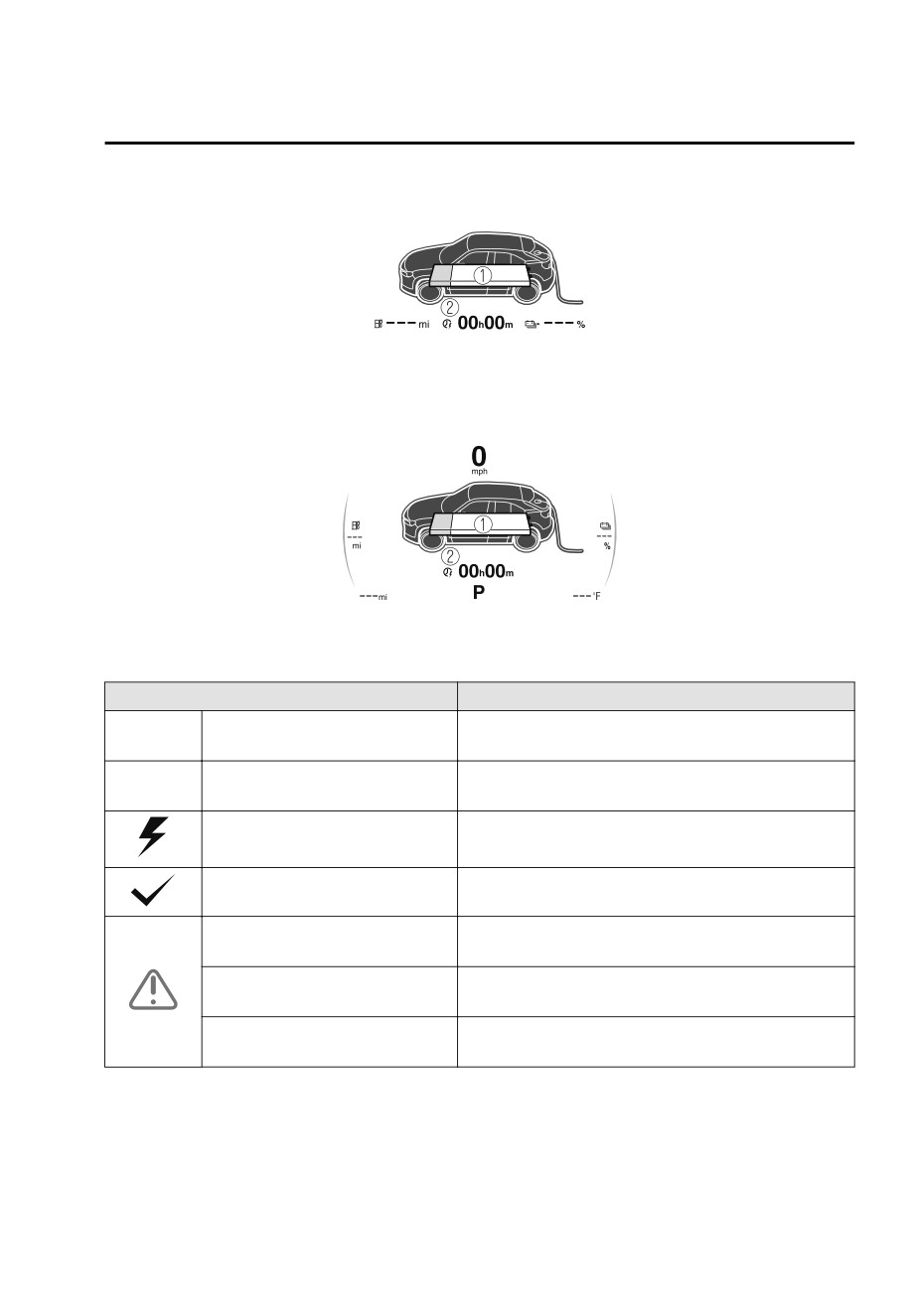
Multi-information Display
When the driver's door is opened with the charge connector connected, the
charging status is displayed on the multi-information display.
3-18
Before Driving
Electric Vehicles
Power switch OFF
1. High voltage battery indication
2. Charging completion time
Power switch ON
1. High voltage battery indication
2. Charging completion time
Indication
Content
Displays while the charging timer is being canceled
—
Preparing to Charge
and when the charging connector is connected.
Displays while in charging timer mode and when the
—
Charging Scheduled
charging connector is connected.
Charging
Displays during charging.
Charging Complete
Displays when charging is completed.
Charging Error. Shift Selector Lev-
Displays when charging is started with the selector
er Not in Park
lever in a position other than P.
Charging Interrupted. See Own-
Displays when charging is interrupted.
er's Manual for Details
Charging Error. Have the Vehicle
Displays when charging is not possible due to a
Inspected
charging system problem.
NOTE
When charging is started, the charging status screen is displayed for a while. The
charging status screen turns off after a certain period of time passes or the doors or
liftgate is locked.
The screen is displayed again when the doors or liftgate is unlocked.
3-19