Mazda Engine SKYACTIV-G 2.5. Manual - part 11
MECHANICAL
01-10–28
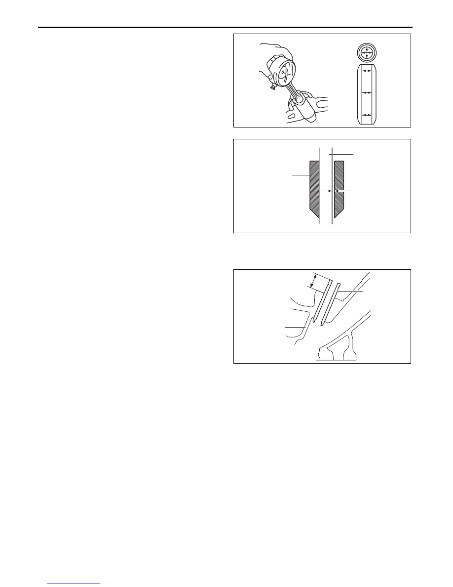
4. Measure the inner diameter of each valve guide
using the caliper gauge. Measurement positions
total six and are in the X and Y directions, at three
points (A, B, and C) as shown in the figure.
• If it is not within the specification, replace the
valve guide.
Standard valve guide inner diameter
IN: 5.510—5.530 mm {0.2170—0.2177 in}
EX: 5.510—5.530 mm {0.2170—0.2177 in}
5. Calculate the clearance between the valve stem
and the valve guide by subtracting the inner
diameter of the valve guide from the outer
diameter of the corresponding valve stem.
• If it exceeds the maximum specification,
replace the valve or valve guide.
Standard clearance between valve stem and
guide
IN: 0.025—0.060 mm {0.0010—0.0023 in}
EX: 0.030—0.065 mm {0.0012—0.0025 in}
Maximum clearance between valve stem and
guide
0.10 mm {0.0039 in}
6. Measure the projection height (dimension A) of
each valve guide using the vernier caliper.
• If it is not within the specification, replace the
valve guide.
Standard valve guide projection height
IN: 16.4—17.0 mm {0.646—0.669 in}
EX: 16.4—17.0 mm {0.646—0.669 in}
End Of Sie
X
Y
A
B
C
bpe2ue00000085
VALVE STEM
CLEARANCE
VALVE GUIDE
bpe2ue00000086
VALVE GUIDE
CYLINDER HEAD
A
bpe2ue00000087