Mazda Engine SKYACTIV-G 2.5. Manual - part 9


  Index      Mazda     Mazda Engine SKYACTIV-G 2.5 - service manual 2012 year


Search            


Content   ..  7  8  9  10   ..


Mazda Engine SKYACTIV-G 2.5. Manual - part 9


MECHANICAL 

01-10–20

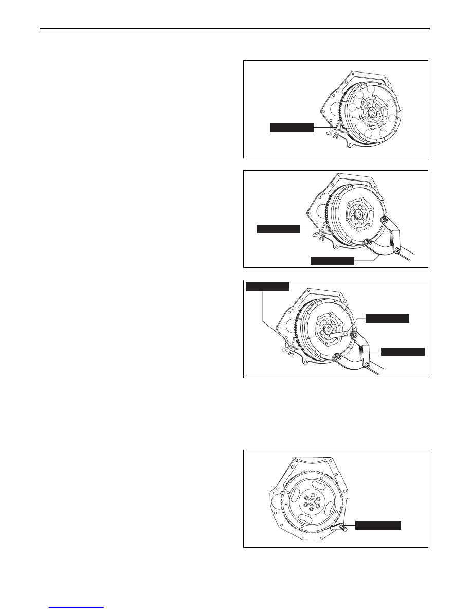
Dual-mass Flywheel (MTX)/ Drive Plate (ATX) Installation Bolt Disassembly Note

Dual-mass flywheel installation bolt (MTX)

1. Hold the crankshaft using the 

SST (49 E011 1A0).

2. Loosen the bolts uniformly and gradually in the 

order shown in the figure.

Note

• If the bolt installation holes are not 

positioned properly, perform the following 

procedure:

(1) Install the 

SST (49 S120 710) to the dual-

mass flywheel.

(2) Rotate the dual-mass flywheel (secondary 

flywheel side) using the 

SST (49 S120 710).

(3) When the bolt installation holes are positioned 

properly, hold the position and remove one of 

the bolts.

(4) After removing the bolt, set up the 

SST (49 

G033 102) to lock the dual-mass flywheel 

(secondary flywheel side) against rotation.

Warning

• If all of the bolts are removed without 

locking the dual-mass flywheel 

(secondary flywheel side) against 

rotation, the dual-mass flywheel (primary 

or secondary flywheel side) may rotate, 

resulting in injury. Therefore, always set 

up the SST (49 G033 102).

• When the bolts are removed from the 

dual-mass flywheel, always cover the bolt 

holes using tape. If the SST (49 G033 102) is removed while the operator’s finger is inserted in the 

bolt hole, the dual-mass flywheel may rotate and the operator could be injured.

(5) Remove the remaining bolts.

Drive plate installation bolt (ATX)

1. Hold the crankshaft using the 

SST.

2. Loosen the bolts uniformly and gradually in the 

order shown in the figure.

8

4

1

6

2

7

5

3

49 E011 1A0

ac5wzw00005660

49 E011 1A0

49 S120 710

am6xuw00005540

49 E011 1A0

49 S120 710

49 G033 102

am6xuw00005541

49 E011 1A0

bpe1ze00000092

MECHANICAL 

01-10–21

01-10

Dual-mass Flywheel Disassembly Note (MTX)

Note

• When reusing the dual-mass flywheel, do not remove the SST (49 G033 102) locking the dual-mass 

flywheel (secondary flywheel side) against rotation.

Rear Oil Seal Disassembly Note

1. Cut the oil seal lip using a utility knife.

2. Remove the oil seal using a flathead screwdriver 

with the tip protected by a clean cloth to prevent 

damage to the oil seal sliding part of the 

crankshaft.

End Of Sie

REAR OIL 
SEAL

CLOTH

bpe5ue00000003

MECHANICAL 

01-10–22

CYLINDER BLOCK DISASSEMBLY (II)

id011000500700

1. Disassemble in the order indicated in the table.

.

5

6

R

2

4

9

7

R

8

15

12

17

11

16

14

13

18

10

7

3

1

SST

R

bpe1ze00000038

1

Pilot bearing (MTX)

(See 01-10-23 Pilot Bearing Disassembly Note.)

2

Connecting rod cap

(See 01-10-23 Connecting Rod Cap Disassembly 

Note.)

3

Lower connecting rod bearing

(See 01-10-23 Connecting Rod Bearing 

Disassembly Note.)

4

Piston, connecting rod

(See 01-10-23 Piston, Connecting Rod Disassembly 

Note.)

5

Upper connecting rod bearing

(See 01-10-23 Connecting Rod Bearing 

Disassembly Note.)

6

Piston ring

7

Snap ring

(See 01-10-24 Snap Ring Disassembly Note.)

8

Piston pin

9

Piston

10

Connecting rod

11

Lower cylinder block

(See 01-10-24 Lower Cylinder Block Disassembly 

Note.)

12

Lower main bearing

(See 01-10-25 Thrust Bearing And Main Bearing 

Disassembly Note.)

MECHANICAL 

01-10–23

01-10

Pilot Bearing Disassembly Note

Note

• The pilot bearing does not need to be removed unless you are replacing it.

1. Use the 

SST to remove the pilot bearing.

Connecting Rod Cap Disassembly Note

1. Before removing the connecting rod cap, inspect 

the connecting rod side clearance. (See 01-10-35 

CONNECTING ROD CLEARANCE 

INSPECTION.)

2. The removed connecting rod caps are to be kept 

so that they can be assembled to the same 

positions and in the direction as before removal.

Connecting Rod Bearing Disassembly Note

1. The removed connecting rod bearings are to be kept so that they can be assembled to the same positions and 

in the direction as before removal.

Piston, Connecting Rod Disassembly Note

1. Before removing the piston and connecting rod, remove the carbon in the cylinder.

2. Before removing the piston and connecting rod, inspect the oil clearance at the large end of the connecting rod. 

(See 01-10-35 CONNECTING ROD CLEARANCE INSPECTION.)

13

Crankshaft

(See 01-10-25 Crankshaft Disassembly Note.)

14

Plate

15

Upper main bearing

(See 01-10-25 Thrust Bearing And Main Bearing 

Disassembly Note.)

16

Thrust bearing

(See 01-10-25 Thrust Bearing And Main Bearing 

Disassembly Note.)

17

Oil jet valve

18

Upper cylinder block

49 1285 071

bpe2ue00000021

bp31je00000044


Content   ..  7  8  9  10   ..