Mazda 6. Manual - part 336
 

  Index      Mazda     Mazda 6 - service repair manual 2002 year


Search            


Content   ..  334  335  336  337   ..


Mazda 6. Manual - part 336


AUDIO AND NAVIGATION SYSTEM 

T–103

T

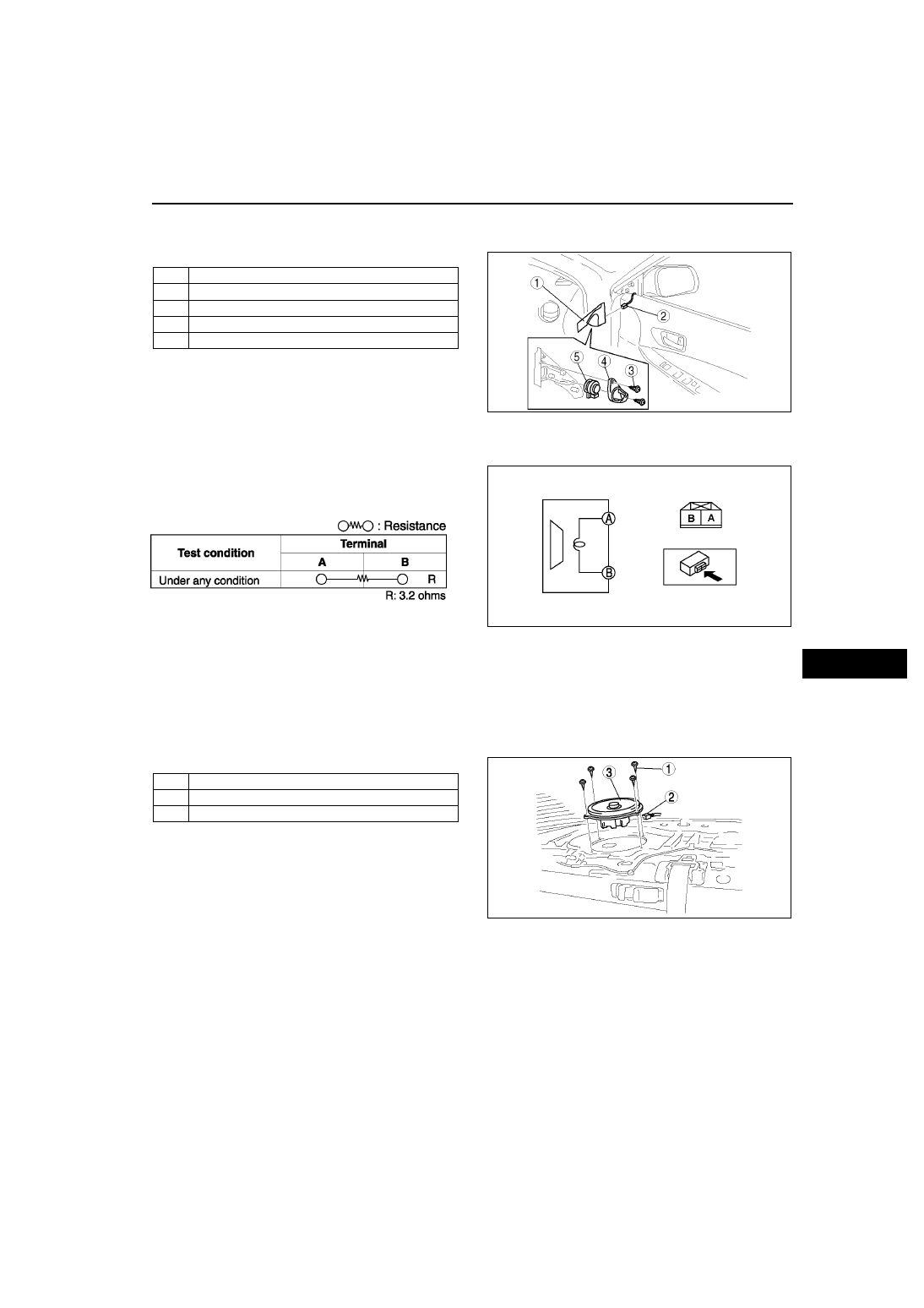
TWEETER REMOVAL/INSTALLATION

A6E812468966W01

1. Disconnect the negative battery cable.
2. Remove in the order indicated in the table.

3. Install in the reverse order of removal.

End Of Sie

TWEETER INSPECTION

A6E812468966W02

1. Inspect for resistance between the tweeter 

terminals using an ohmmeter.

• If not as specified, replace the tweeter.

2. To verify that the tweeter outputs sound, apply 

voltage to the tweeter and release using a 1.5-V 
battery.

• If not outputs sound, replace the tweeter.

End Of Sie

WOOFER REMOVAL/INSTALLATION

A6E812466967W01

4SD

1. Disconnect the negative battery cable.
2. Remove the rear package trim.
3. Remove in the order indicated in the table.

4. Install in the reverse order of removal.

1

Inner garnish

2

Connector

3

Screw

4

Cover

5

Tweeter

A6E8124W004

A6E8124W041

A6E8124W033

1

Screw

2

Connector

3

Woofer

A6E8124W005

T–104

AUDIO AND NAVIGATION SYSTEM 

5HB

1. Disconnect the negative battery cable.
2. Remove in the order indicated in the table.

3. Install in the reverse order of removal.

End Of Sie

WOOFER INSPECTION

A6E812466967W02

1. Inspect for continuity between the audio amplifier 

connector terminals and woofer connector 
terminals using an ohmmeter.

• If not as specified, replace the related wiring 

harnesses.

2. Verify that there is battery positive voltage at the 

woofer connector terminal A (4SD) or C (5HB) 
using a voltmeter.

• If not as specified, replace the related wiring 

haness.

3. Inspect continuity between the woofer connector 

terminal B and body ground using an ohmmeter.

• If not as specified, replace the related wiring 

harness.

• If as specified, replace the woofer.

End Of Sie

NOISE FILTER REMOVAL/INSTALLATION

A6E812466869W01

Brake Light Noise Filter

1. Disconnect the negative battery cable.
2. Remove in the order indicated in the table.

3. Install in the reverse order of removal.

1

Temporary spare tire cover

2

Wing bolt

3

Connector

4

Woofer

A6E8124W006

A6E8124W046

A6E8124W024

1

Nut

2

Connector

3

Noise filter

A6E8124W008

AUDIO AND NAVIGATION SYSTEM 

T–105

T

Rear Window Defroster Noise Filter

1. Disconnect the negative battery cable.
2. Remove the rear package trim.
3. Remove in the order indicated in the table.

4. Install in the reverse order of removal.

End Of Sie

NOISE FILTER INSPECTION

A6E812466869W02

Brake Light Noise Filter

1. Inspect for resistance and continuity between the 

noise filter terminals using an ohmmeter.

• If not as specified, replace the noise filter.

1

Bolt

2

Connector

3

Noise filter

A6E8124W009

A6E8124W034

A6E8124W035

T–106

AUDIO AND NAVIGATION SYSTEM 

Rear Window Defroster Noise Filter

1. Inspect for resistance and continuity between the 

noise filter terminals using an ohmmeter.

• If not as specified, replace the noise filter.

End Of Sie

CONDENSER REMOVAL/INSTALLATION

A6E812466869W03

4SD

1. Disconnect the negative battery cable.
2. Remove the rear package trim.
3. Remove in the order indicated in the table.

4. Install in the reverse order of removal.

5HB

1. Disconnect the negative battery cable.
2. Remove the liftgate lower trim.
3. Remove in the order indicated in the table.

4. Install in the reverse order of removal.

End Of Sie

A6E8124W036

A6E8124W037

1

Bolt

2

Connector

3

Condenser

A6E8124W007

1

Bolt

2

Connector

3

Condenser

A6E8124W021


Content   ..  334  335  336  337   ..