Mazda 6. Manual - part 316
 

  Index      Mazda     Mazda 6 - service repair manual 2002 year


Search            


Content   ..  314  315  316  317   ..


Mazda 6. Manual - part 316


T–24

POWER SYSTEM 

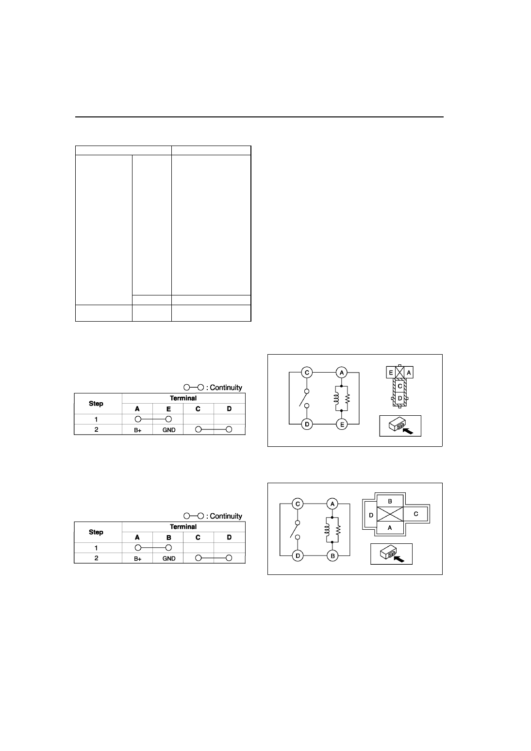
RELAY INSPECTION

A6E811067730W02

Relay Type

Four-terminal
Type A

1. Remove the relay.
2. Inspect for continuity between the relay terminals 

using an ohmmeter.

• If not as specified, replace the relay.

Type B

1. Remove the relay.
2. Inspect for continuity between the relay terminals 

using an ohmmeter.

• If not as specified, replace the relay.

Terminal type

Parts name

Four-terminal

Type A

• Main relay

• Fuel pump relay

• Stater relay

• TNS relay

• Front fog light relay

• Rear fog light relay

• Horn relay

• Headlight cleaner 

relay

• Rear window 

defroster relay

• Woofer relay

• A/C relay

• Blower relay

• Cooling fan relay No.1 

(except L3 engine)

• Cooling fan relay No.2

• Cooling fan relay No.3

• Cooling fan relay No.4

Type B

• Headlight relay

Five-terminal

Type C

• Cooling fan relay No.1 

(L3 engine only)

A6E8110W118

A6E8110W121

A6E8110W125

A6E8110W123

POWER SYSTEM, EXTERIOR LIGHTING SYSTEM 

T–25

T

Type C

1. Remove the relay.
2. Inspect for continuity between the relay terminals 

using an ohmmeter.

• If not as specified, replace the relay.

End Of Sie

DISCHARGE HEADLIGHT SERVICE WARNINGS

A6E811251060W01

Discharge headlight bulb service warnings

• To prevent electrical shock when replacing the discharge headlight bulb, dry hands thoroughly, and 

carry out work in an area out of rain.

• When the light switch is on, approx. 25,000 V 

of high voltage passes through the discharge 
headlight bulb socket. Because of the danger 
of electrical shock, do not insert fingers or a 
circuit tester.

• When the headlights are on, high voltage 

flows around the socket and bulb. When 
turning on the discharge headlights while 
working, always leave the headlights in the 
vehicle-installed condition to prevent 
electrical shock.

Discharge headlight control unit service warnings

• Because of the danger of electrical shock, 

when inspecting with a circuit tester or similar 
device, do not inspect the discharge headlight 
control unit as a single unit or disassemble it.

• If there are scratches or damage to the 

discharge headlight control unit, or it has 
been impacted, there may be damage despite 
apparent normal operation. Therefore, to 
prevent electrical shock or operation error, 
replace with new parts.

End Of Sie

A6E8110W122

A6E8110W126

EXTERIOR LIGHTING SYSTEM

A6E8112W163

A6E8112W164

T–26

EXTERIOR LIGHTING SYSTEM 

FRONT COMBINATION LIGHT REMOVAL/INSTALLATION

A6E811251060W02

Caution

• Incorrect servicing of the discharge headlights could result in electrical shock. Before servicing 

the discharge headlights, always refer to the “Discharge headlight service warnings.” (See 

T–25 

DISCHARGE HEADLIGHT SERVICE WARNINGS

)

Note

• When the ignition switch is turned to ON, it is normal to hear the headlight leveling actuator operating for a 

few second, as it verifies headlight auto leveling system operating condition.

1. Disconnect the negative battery cable.
2. Remove the front bumper. (See 

S–47 FRONT BUMPER REMOVAL/INSTALLATION

)

3. Remove in the order indicated in the table.

4. Install in the reverse order of removal.
5. Adjust the headlight aiming. (See 

T–26 

HEADLIGHT AIMING

.)

End Of Sie

HEADLIGHT AIMING

A6E811251030W01

Low-beam

1. Set up a screen as shown in the figure below for 

aiming the headlights.

2. Adjust the tire air pressure to the specification.
3. Position the unloaded vehicle on a flat, level 

surface.

4. Seat one person in the driver's seat.
5. Position the vehicle straight ahead and 

perpendicular to a wall.

1

Connector

2

Bolt

3

Clip

4

Cover

5

Front combination light

A6E8112W101

A6E8112W132

A6E8112W133

EXTERIOR LIGHTING SYSTEM 

T–27

T

6. Set the headlights 3 m {10 ft} from the wall.
7. While adjusting one headlight, mask the other.
8. Start the engine to charge the battery.
9. Turn on the lower-beam headlight.

10. Set the headlight leveling switch to 0 position.
11. Adjust the headlights by turning the adjusting 

screws as shown in the figure. Loosen the screws 
first, then tighten them.

Note

• If the adjusting screws are tightened first, 

then loosened, they will continue to loosen 
when the vehicle is in motion and may cause 
the headlights to become misaligned.

12. Turn the adjusting screws and adjust the 

headlight so that the elbow point in the shaded 
area in the figure.

High-beam

1. Adjust the tire air pressure to the specification.
2. Position the unloaded vehicle on a flat, level surface.
3. Seat one person in the driver's seat.
4. Position the vehicle straight ahead and perpendicular to a wall.

A6E8112W157

A6E8112W125

A6E8112W134

A6E8112W135


Content   ..  314  315  316  317   ..