Mazda 6. Manual - part 274
 

  Index      Mazda     Mazda 6 - service repair manual 2002 year


Search            


Content   ..  272  273  274  275   ..


Mazda 6. Manual - part 274


REAR SUSPENSION 

R–31

R

REAR UPPER ARM REMOVAL/INSTALLATION

A6E741628210W01

Caution

• Performing the following procedures without first removing the ABS wheel-speed sensor may 

possibly cause an open circuit in the harness if it is pulled by mistake. Before performing the 
following procedures, remove the ABS wheel-speed sensor (axle side) and fix it to an appropriate 
place where the sensor will not be pulled by mistake while servicing the vehicle.

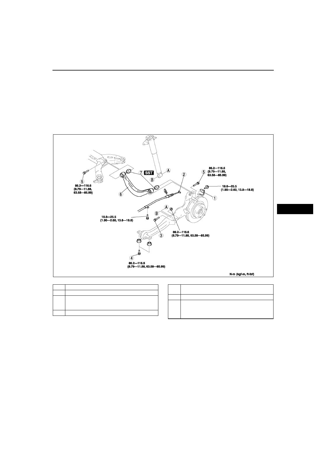
1. Remove in the order indicated in the table.
2. Install in the reverse order of removal.
3. Inspect the rear wheel alignment.

(See 

R–6 REAR WHEEL ALIGNMENT

.)

.

A6E7416W009

1

ABS wheel-speed sensor

2

Parking brake cable

3

Bolt (rear shock absorber lower side)
(See 

R–32 Bolt (Rear Shock Absorber Lower Side) 

Removal Note

)

4

Bolt (trailing link front side)

5

Bolt (rear upper arm)
(See 

R–32 Bolt (Rear Upper Arm) Removal Note

)

6

Rear upper arm

7

Rear upper arm bushing
(See 

R–32 Rear Upper Arm Bushing Removal Note

)

(See 

R–32 Rear Upper Arm Bushing Installation 

Note

)

R–32

REAR SUSPENSION 

Bolt (Rear Shock Absorber Lower Side) Removal Note

1. Support the trailing link with a jack.

Bolt (Rear Upper Arm) Removal Note

1. Loosen the bolts on the inner and outer side of the lateral link.

Rear Upper Arm Bushing Removal Note

1. Press the upper arm bushing out using the SSTs.

Rear Upper Arm Bushing Installation Note

1. Mark the new bushing as shown in the figure.

2. Press the bushing in to the marking using the 

SSTs.

A6E7416W005

A6E7416W010

A6E7416W011

A6E7416W012

REAR SUSPENSION 

R–33

R

3. Verify that clearance distance A—B is 14.0 mm—

16.0 mm {0.56 in-0.62 in}.

End Of Sie

REAR LATERAL LINK REMOVAL/INSTALLATION

A6E741628600W01

1. Remove the rear lateral link.

Caution

• When working near left rear suspension, avoid any impact to the fuel tank.

2. Measure the length L shown in the figure for 

proper installation.

3. Temporarily loosen a locknut of the rear lateral 

link.

4. Install the rear lateral link.
5. Inspect the rear wheel alignment.

(See 

R–6 REAR WHEEL ALIGNMENT

.)

A6E7416W013

B6U0214W015

A

C

C

A

D

D

B

B

93.1—126.4
{9.50—12.88, 68.67—93.22}

REAR
LATERAL
LINK

N·m {kgf·m, ft·lbf}

93.1—126.4
{9.50—12.88, 
68.67—93.22}

B6U0214W014

L

R–34

REAR SUSPENSION 

End Of Sie

REAR STABILIZER REMOVAL/INSTALLATION

A6E741628100W01

1. Remove the rear auto leveling sensor.

(See 

T–32 REAR AUTO LEVELING SENSOR REMOVAL/INSTALLATION

.)

2. Remove in the order indicated in the table.
3. Install in the reverse order of removal.
4. Adjust the headlight zeroset.

(See 

T–31 HEADLIGHT ZEROSET

.)

.

End Of Sie

A6E7416W004

1

Stabilizer control link

2

Stabilizer bracket

3

Bushing

4

Rear stabilizer


Content   ..  272  273  274  275   ..