Mazda 6. Manual - part 127
 

  Index      Mazda     Mazda 6 - service repair manual 2002 year


Search            


Content   ..  125  126  127  128   ..


Mazda 6. Manual - part 127


F–44

CONTROL SYSTEM 

European (L.H.D.) specs.

.

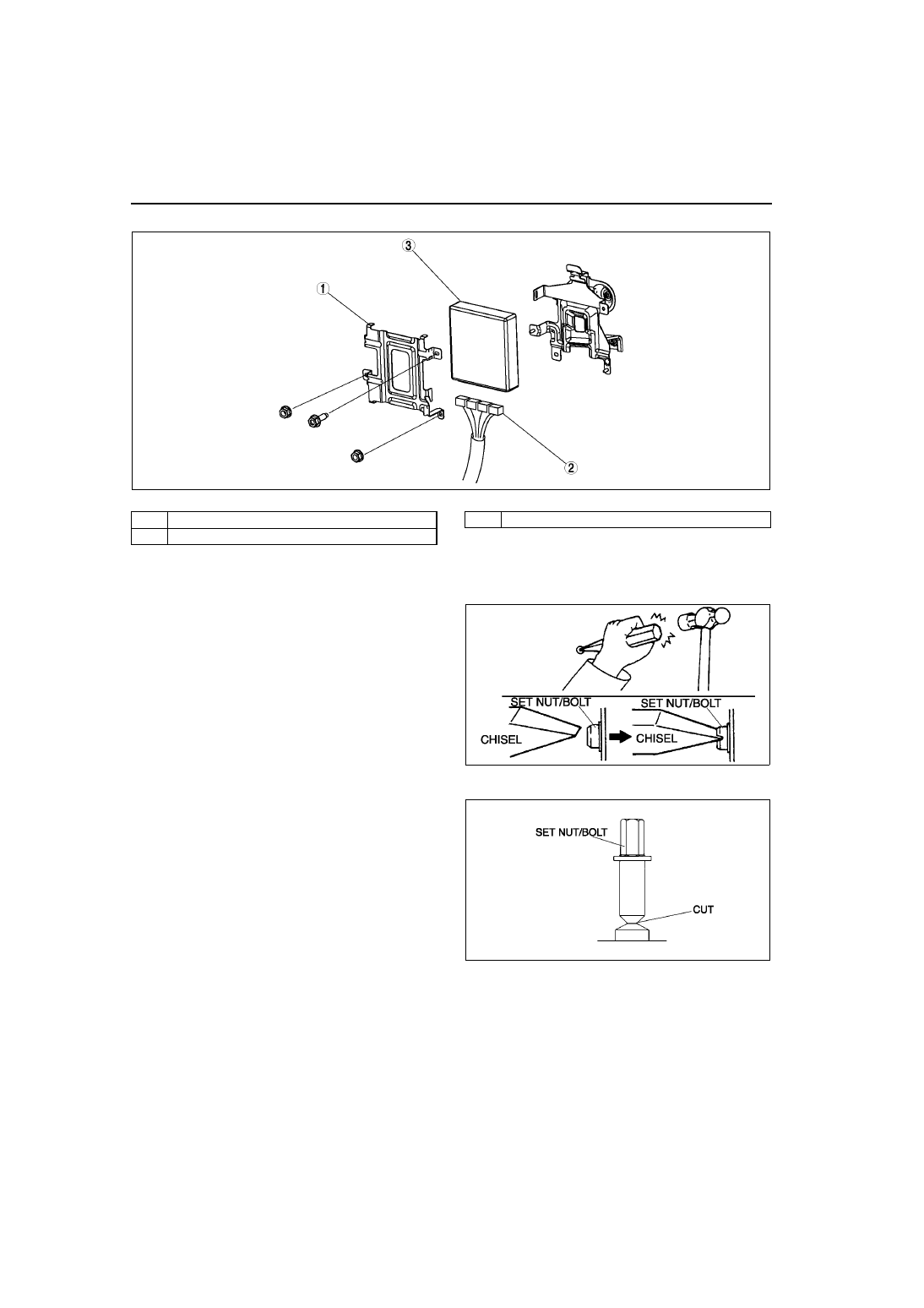
Set Nut/bolt Removal Note

1. Using a chisel and a hammer, cut a groove on the head of the set nut/bolt so that a screwdriver can be 

inserted.

2. Loose the set nut/bolt using an impact 

screwdriver or pliers.

Set Nut/bolt Installation Note

1. Install a new set nut/bolt and tighten it until the 

neck of the nut/bolt is cut.

End Of Sie

A6E3940W001

1

PCM cover

2

PCM connector

3

PCM

A6E3940W003

A6E3940W004

CONTROL SYSTEM 

F–45

F

PCM INSPECTION

A6E394018880W02

Using SST (WDS or Equivakent)

Note

• PIDs for the following parts are not available on this model. Go to the appropriate part inspection page.

— CMP sensor (See 

F–55 CAMSHAFT POSITION (CMP) SENSOR INSPECTION

.)

— Main relay (See 

T–24 RELAY INSPECTION

.)

1. Connect the SST (WDS or equivalent) to the 

DLC-2.

2. Turn the ignition switch to ON position.
3. Measure the PID value.

• If PID value is not within the specification, 

follow the instructions in Action column.

Note

• The PID/DATA MONITOR function monitors 

the calculated value of the input/output 
signals in the PCM. Therefore, an output 
device malfunction is not directly indicated 
as a malfunction of the monitored value for 
the output device. If a monitored value of an 
output device is out of specification, inspect the monitored value of the input device related to the output 
control.

• For input/output signals except those of the monitoring items, use a voltmeter to measure the PCM 

terminal voltage.

• The simulation items that are used in the ENGINE CONTROL SYSTEM OPERATION INSPECTION are 

as follows.
— ACCS
— ALTF
— EVAPCP
— FAN1
— FAN2
— FAN3
— FP
— HTR11
— HTR12
— IAC
— IASV
— IMRC
— IMTV
— VT DUTY1

PID/DATA monitor table (reference)

DLC-2

A6E3970W002

Monitor item 

(Definition)

Unit/

Condition

Condition/Specification 

(Reference)

Action

PCM 

terminal

ACCS (A/C relay)

ON/OFF

Ignition switch ON: OFF
A/C switch ON and fan switch ON at 
idle: ON

Inspect following PIDs: RPM, TP, 
ECT, ACSW, TR.
Inspect A/C relay.
(See 

U–47 CLIMATE CONTROL 

UNIT INSPECTION

)

4O

ACSW (A/C switch)

ON/OFF

A/C switch and fan switch ON at 
ignition switch ON: OFF
A/C switch OFF at ignition switch 
ON: OFF

Inspect A/C switch.
(See 

U–47 CLIMATE CONTROL 

UNIT INSPECTION

)

1AC

ALTF (Generator field 
coil control duty value)

%

Ignition switch ON: 0%
Idle: 0—100%
Just after A/C switch ON and fan 
switch ON at idle: Duty value rises

Inspect following PIDs: IAT, ECT, 
RPM, VPWR, ALTT V.
Inspect generator.
(See 

G–7 GENERATOR 

INSPECTION

)

1AD

ALTT V (Generator 
output voltage)

V

Ignition switch ON: 0 V
Idle: Approx. 14.9 V

*1 

(E/L not 

operating)

Inspect generator.
(See 

G–7 GENERATOR 

INSPECTION

)

1AA

F–46

CONTROL SYSTEM 

ARPMDES
(Target engine speed)

RPM

L8

No load: 700 rpm
E/L operating: 700 rpm
P/S operating: 750 rpm
A/C ON: 750 rpm

LF MTX and L3 MTX

No load: 650 rpm
E/L operating: 700 rpm
P/S operating: 700 rpm
A/C ON: 750 rpm

LF ATX

No load: 700 rpm
E/L operating: 700 rpm
P/S operating: 700 rpm
A/C ON: 700 rpm*

2

, 750 rpm*

3

Inspect following PIDs: IAT, RPM, 
MAP, ECT, MAF, TP, INGEAR, 
ACSW, TR, PSP, ALTT V.
Inspect IAC valve.
(See 

F–13 IDLE AIR CONTROL 

(IAC) VALVE INSPECTION

)

Inspect CKP sensor.
(See 

F–54 CRANKSHAFT POSITION 

(CKP) SENSOR INSPECTION

)

AST (After start timer)

Time

BARO 
(Barometric pressure)

Pressure

Ignition switch ON (at sea level): 
approx 101 kPa

Inspect BARO sensor.
(See 

F–60 BAROMETRIC 

PRESSURE (BARO) SENSOR 
INSPECTION

)

1G

V

Ignition switch ON (at sea level): 
approx 4.1 V

BOO
(Brake switch)

ON/OFF

Brake pedal depressed: ON
Brake pedal released: OFF

Inspect brake switch.
(See 

P–8 BRAKE SWITCH 

INSPECTION

)

1K

CHRGLMP (Generator 
warning light)

ON/OFF

Ignition switch ON: ON
Idle: OFF

Perform applicable DTC 
troubleshooting.
(See 

F–67 DTC TABLE

)

COLP (Refrigerant 
pressure switch 
(middle))*

4

ON/OFF

Refrigerant pressure switch (middle) 
ON 

*2

 at idle: ON

Refrigerant pressure switch (middle) 
OFF

*3

 at idle: OFF

Inspect refrigerant pressure switch.
(See 

U–43 REFRIGERANT 

PRESSURE SWITCH INSPECTION

)

1Q

CPP
(Clutch pedal position)

ON/OFF

Clutch pedal depressed: ON
Clutch pedal released: OFF

Inspect clutch switch.
(See 

F–59 CLUTCH SWITCH 

INSPECTION

)

1R

CPP/PNP (Shift lever 
position)

ON/OFF

Neutral position: ON
Others: OFF

Inspect neutral switch.
(See 

F–59 NEUTRAL SWITCH 

INSPECTION

)

1W

DTCCNT (Number of 
DTC detected)

Perform applicable DTC 
troubleshooting.
(See 

F–67 DTC TABLE

)

ECT (Engine coolant 
temperature)

°C

°F

ECT 20 

°C {68 °F}: 20 °C {68 °F}

ECT 60 

°C {140 °F}: 60 °C {140 °F}

Inspect ECT sensor.
(See 

F–53 ENGINE COOLANT 

TEMPERATURE (ECT) SENSOR 
INSPECTION

)

1M

V

ECT 20 

°C {68 °F}: 3.04—3.14 V

ECT 60 

°C {140 °F}: 1.29—1.39 V

EVAPCP (Purge 
solenoid valve duty 
value)

%

Ignition switch ON: 0%
Idle: 0%

Inspect following PIDs: IAT, RPM, 
ECT, MAF, O2S11,BARO, INGEAR, 
TR, VPWR.
(See 

F–39 PURGE SOLENOID 

VALVE INSPECTION

)

4U

FAN1
(Cooling fan control)

ON/OFF

ECT below 100 

°C {212 °F}: OFF

Others: ON

Inspect following PIDs: RPM, TP, 
ECT, ACSW, COLP, TEST.
Inspect cooling fan relay.
(See 

T–24 RELAY INSPECTION

)

4L

FAN2
(Cooling fan control)

ON/OFF

ECT below 108 

°C {226 °F}: OFF

A/C operating, refrigerant pressure 
switch (middle) is OFF, and ECT 
below 108 

°C {226 °F}: OFF

Others: ON

Inspect following PIDs: RPM, TP, 
ECT, ACSW, COLP, TEST.
Inspect cooling fan relay.
(See 

T–24 RELAY INSPECTION

)

4F

FAN3
(Cooling fan control)

ON/OFF

ECT below 100 

°C {212 °F}: OFF

A/C operating, refrigerant pressure 
switch (middle) is ON, and ECT 
below 108 

°C {226 °F}: OFF

Other: ON

Inspect following PIDs: RPM, TP, 
ECT, ACSW, COLP, TEST.
Inspect cooling fan relay.
(See 

T–24 RELAY INSPECTION

)

4B

Monitor item 

(Definition)

Unit/

Condition

Condition/Specification 

(Reference)

Action

PCM 

terminal

CONTROL SYSTEM 

F–47

F

FDPDTC
(Pending code caused 
FFD storage)

Perform applicable DTC 
troubleshooting.
(See 

F–67 DTC TABLE

)

FP (Fuel pump relay)

ON/OFF

Ignition switch ON: OFF
Idle: ON
Cranking: ON

Inspect following PIDs: RPM.
Inspect fuel pump relay.
(See 

T–24 RELAY INSPECTION

)

4P

*5

4Q

*6

FUELPW (Fuel injector 
duration)

TIME

Ignition switch ON: 0 ms
Idle (after warm up): approx. 2.5 ms

Inspect following PIDs: IAT, MAF, TP, 
MAP, ECT, RPM, O2S11, O2S12, 
INGEAR, TR, PSP, ACSW, VPWR, 
ALTT V.
Inspect fuel injector.
(See 

T–24 RELAY INSPECTION

)

4W, 4Z, 

4AA, 

4AD

FUELSYS
(Fuel system status)

Open loop/

Closed loop

Ignition switch ON: Open loop
Idle (after warm up): Closed loop

Inspect following PIDs: IAT, MAF, TP, 
MAP, ECT, RPM, O2S11, O2S12, 
INGEAR, TR, PSP, ACSW, VPWR, 
ALTT V.
Inspect fuel injector.
(See 

T–24 RELAY INSPECTION

)

GENVDSD
(Generator voltage 
desired)

V

Ignition switch ON: 0 V
Idle: Approx. 14.9 V

*1 

(E/L not 

operating)

Perform applicable DTC 
troubleshooting.
(See 

F–67 DTC TABLE

)

HTR11
(HO2S heater (front))

ON/OFF

Idle (after warm up): ON

⇔OFF

Inspect following PIDs: IAT, MAF, TP, 
ECT, RPM, ACSW.
(See 

F–56 HEATED OXYGEN 

SENSOR (HO2S) INSPECTION

)

4A

HTR12
(HO2S heater (rear))

ON/OFF

Ignition switch ON: OFF (HO2S 
heater not operating)
Idle: ON (HO2S heater operating)

Inspect following PIDs: IAT, MAF, 
ECT, RPM, ACSW.
(See 

F–56 HEATED OXYGEN 

SENSOR (HO2S) INSPECTION

)

4D

IAC (IAC valve)

%

Ignition switch ON: 0%
Idle: Approx. 60% (ECT 90

°C {194 

°F} and E/L not operating) 

Inspect following PIDs: IAT, RPM, 
MAP, ECT, MAF, TP, INGEAR, TR, 
PSP, ACSW.
Inspect IAC valve.
(See 

F–13 IDLE AIR CONTROL 

(IAC) VALVE INSPECTION

)

4G

4J

IASV (Variable air duct 
control solenoid valve)

ON/OFF

ECT is above 70 

°C {158 °F}, engine 

speed is above 5,800 rpm, and TP 
opening angle is above 50%: ON
Others: OFF

Inspect following PIDs: ECT, RPM, 
TP.
Inspect VAD control solenoid valve.
(See 

F–13 VARIABLE AIR DUCT 

(VAD) CONTROL SOLENOID VALVE 
INSPECTION (L3)

4C

IAT
(Intake air temperature)

°C

°F

IAT 20 

°C {68 °F}: 20 °C {68 °F}

IAT 30 

°C {86 °F}: 30 °C {86 °F}

Inspect IAT sensor.
(See 

F–50 INTAKE AIR 

TEMPERATURE (IAT) SENSOR 
INSPECTION

)

2E

V

IAT 20 

°C {68 °F}: 2.4—2.6 V

IAT 30 

°C {86 °F}: 1.7—1.9 V

IMRC (Variable tumble 
control solenoid valve)

ON/OFF

Engine speed is below approx. 
3,750 rpm: ON
Others: OFF

Inspect following PIDs: TP, ECT, 
RPM.
Inspect VTCS solenoid valve.
(See 

F–15 VARIABLE TUMBLE 

CONTROL SOLENOID VALVE 
INSPECTION

)

4T

IMTV (Variable Intake-
air control solenoid 
valve)

ON/OFF

Engine speed is below approx. 
4,500 rpm: ON
Others: OFF

Inspect following PIDs: RPM.
Inspect VIS control solenoid valve.
(See 

F–14 VARIABLE INTAKE-AIR 

SYSTEM (VIS) CONTROL 
SOLENOID VALVE INSPECTION 
(L3)

)

4R

INGEAR (Load/no load 
condition)

ON/OFF

CPP or CPP/PNP is ON: OFF
Others: ON

Perform applicable DTC 
troubleshooting.
(See 

F–67 DTC TABLE

)

1R, 1W

IVS (CTP condition)

ON/OFF

CTP: ON
Others: OFF

Perform applicable DTC 
troubleshooting.
(See 

F–67 DTC TABLE

)

2A

Monitor item 

(Definition)

Unit/

Condition

Condition/Specification 

(Reference)

Action

PCM 

terminal


Content   ..  125  126  127  128   ..