Mazda 6. Manual - part 108
 

  Index      Mazda     Mazda 6 - service repair manual 2002 year


Search            


Content   ..  106  107  108  109   ..


Mazda 6. Manual - part 108


REAR OIL SEAL 

B–25

B

REAR OIL SEAL REPLACEMENT

A6E222211399W01

1. Remove the flywheel. (MTX) (See 

H–11 CLUTCH UNIT REMOVAL/INSTALLATION

)

2. Remove the drive plate. (ATX) (See 

K–43 DRIVE PLATE REMOVAL/INSTALLATION

)

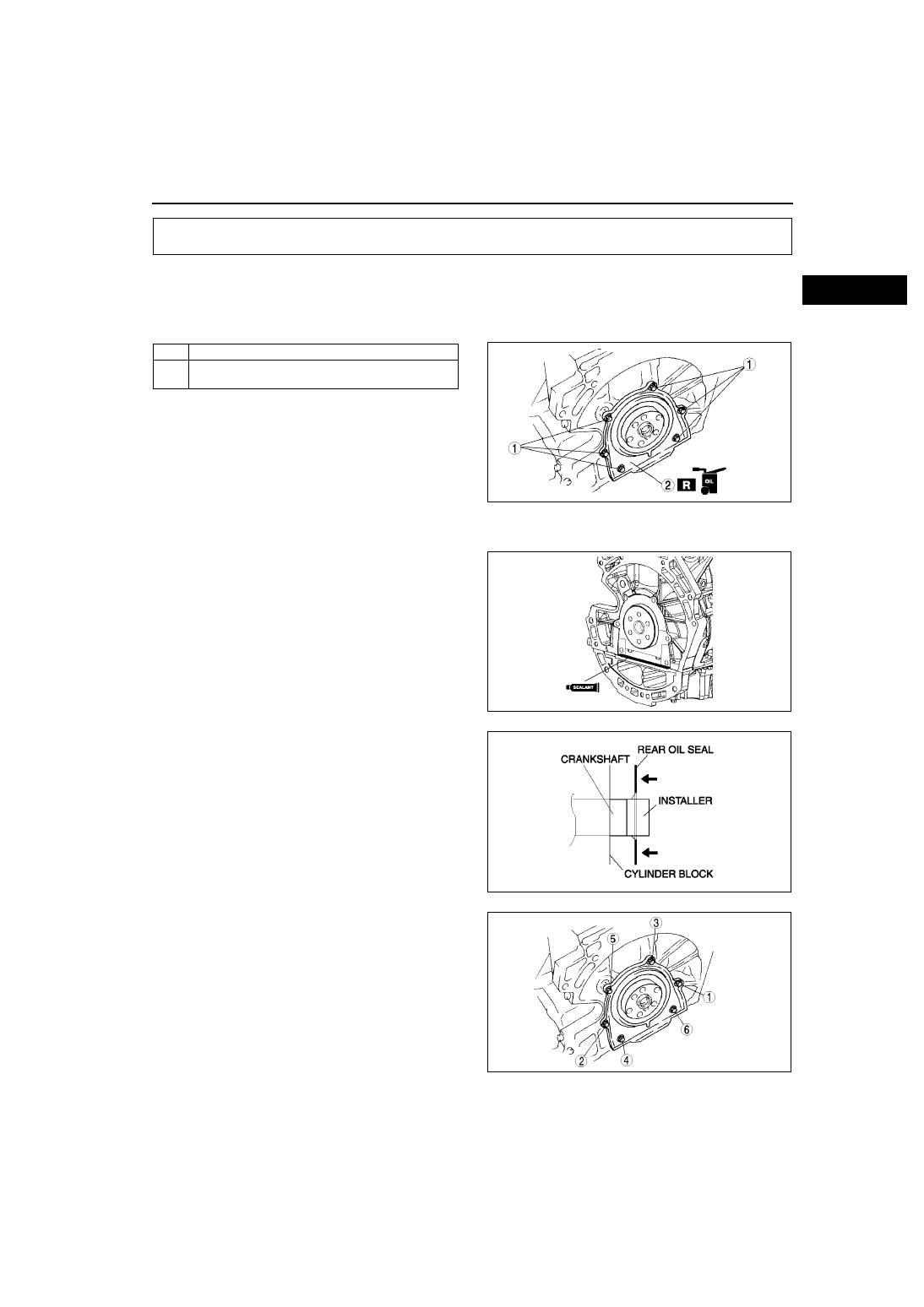
3. Remove in the order indicated in the table.
4. Install in the reverse order of removal.

.

Rear Oil Seal Installation Note

1. Apply silicone sealant to the mating faces as 

shown.

Dot diameter:
 4.0—6.0 mm {0.16—0.23 in}

2. Apply clean engine oil to the new oil seal lip.

3. Install the rear oil seal using the installer as 

shown.

4. Tighten the rear oil seal bolts in the order as 

shown.

Tightening torque:

8.0—11.5 N·m {81.6—117.2 kgf·m, 70.9—

101.7 in·lbf}

End Of Sie

REAR OIL SEAL

1

Bolt

2

Rear oil seal
(See 

B–25 Rear Oil Seal Installation Note

)

AME2222W001

AME2222W002

AME2224E326

AME2222W004

B–26

ENGINE 

ENGINE REMOVAL/INSTALLATION

A6E222401001W01

Warning

• Fuel vapor is hazardous. It can very easily ignite, causing serious injury and damage. Always keep 

sparks and flames away from fuel.

• Fuel line spills and leakage are dangerous. Fuel can ignite and cause serious injures or death and 

damage. Fuel can also irritate skin and eyes. To prevent this, always complete the “Fuel Line 
Safety Procedure”. (See 

F–17 Fuel Line Safety Procedure

.)

1. Remove the battery. (See 

G–3 BATTERY REMOVAL/INSTALLATION

.)

2. Remove the battery tray. (See 

G–3 BATTERY REMOVAL/INSTALLATION

.)

3. Remove the radiator. (See 

E–6 RADIATOR REMOVAL/INSTALLATION

.)

4. Drain the missions oil.
5. Remove the P/S oil pump with the oil hose still connected and position the P/S oil pump so that it is out of the 

way. (See

N–22 POWER STEERING OIL PUMP REMOVAL/INSTALLATION

)

6. Remove the A/C compressor with the pipes still connected. Position the A/C compressor so that it is out of the 

way. Use wire or rope to secure.

7. Remove the joint shaft from the front drive shaft. (See 

M–17 DRIVE SHAFT REMOVAL/INSTALLATION

.)

8. Remove the air cleaner, intake air duct, accelerator cable and bracket, and vacuum hose. (See 

F–10 

INTAKE-AIR SYSTEM REMOVAL/INSTALLATION

.)

9. Remove the ATF filter and selector cable. (ATX) (See 

K–29 AUTOMATIC TRANSAXLE REMOVAL/

INSTALLATION

.)

10. Remove the vacuum hose and heater hose.
11. Remove the release cylinder and control cable. (MTX) (See 

J–5 MANUAL TRANSAXLE REMOVAL/

INSTALLATION

.)

12. Remove the plastic fuel hose. (See 

F–23 Plastic Fuel Hose Removal Note

.) (See 

F–24 Plastic Fuel Hose 

Installation Note

.)

13. Disconnect the wiring harness from the engine side.
14. Remove the front pipe. (See 

F–35 EXHAUST SYSTEM REMOVAL/INSTALLATION

.)

15. Remove in the order indicated in the table.
16. Install in the reverse order of removal.
17. Start the engine and:

• Inspect for the engine oil, engine coolant, transaxle oil and fuel leakage.

• Verify the ignition timing, idle speed and idle mixture. (See 

F–8 IGNITION TIMING INSPECTION

.) (See

F–9 

IDLE MIXTURE INSPECTION

.)

18. Perform a road test.

ENGINE

ENGINE 

B–27

B

.

AME2213W001

1

No.1 Engine mount rubber 
(See 

B–28 No.1 Engine Mount Rubber Removal 

Note

(See 

B–31 No.1 Engine Mount Rubber Installation 

Note

)

2

No.1 Engine mount bracket 
(See 

B–31 No.1 Engine Mount Bracket Installation 

Note

)

3

No.4 Engine mount bracket and No.4 Engine mount 
rubber
(See 

B–28 No.4 Engine Mount Bracket and No.4 

Engine Mount Rubber Removal Note

(See 

B–30 No.4 Engine Mount Bracket and No.4 

Engine Mount Rubber Installation Note

)

4

Engine ground

5

No.3 Engine joint bracket (See 

B–29 No.3 Engine 

Joint Bracket Installation Note

)

6

Engine, transaxle

B–28

ENGINE 

No.1 Engine Mount Rubber Removal Note

1. Suspend the engine using the SSTs.
2. Remove the through bolt A on the No.1 engine 

mount bracket side.

3. Loosen the through bolt B on the chassis side 

until approximately three pitches are showing.

Note

• Do not remove the No.1 engine mount 

rubber from the vehicle.

No.4 Engine Mount Bracket and No.4 Engine Mount Rubber Removal Note

1. Secure the engine and the transaxle using an 

engine jack and attachment as shown.

AME2215W004

AME2213W002

AME2213W003

AME2218W001


Content   ..  106  107  108  109   ..