Lexus LX600 (2024 year). Manual in english - page 10
 

  Index      Manuals     Lexus LX600 (2024 year). Manual in english


Search            copyright infringement  


Content      ..     8      9      10      11     ..


Lexus LX600 (2024 year). Manual in english - page 10


316

4-5. Using the driving support systems

In addition to screen switching by 
operating the VIEW switch, automatic 
display mode is available. In this mode, 
the screen is switched automatically in 
response to vehicle speed.
In automatic display mode, the monitor 
will automatically display images in the 
following situations:

When the shift lever is shifted to N 
or D position.

When vehicle speed is reduced to 
approximately 6 mph (10 km/h) or 
less.

When automatic display mode of the 
Cornering View display is enabled, the 
screen will change automatically 
between the Side Clearance View and 
Cornering View depending on the 
turning angle of the steering wheel.
In automatic display mode of Corner-
ing View, the monitor will automatically 
display Cornering View images in the 
following situations:

When the shift lever is shifted to N 
or D position.

When vehicle speed is reduced to 
approximately 6 mph (10 km/h) or 
less.

When the steering wheel is turned 
by 180° or more from the center 
(straight-line) position.

Cornering View images will disappear 

when the turning angle of the steering 
wheel becomes 90° or less from the 
center (straight-line) position.

Automatic display mode of Cornering 

View

You can change automatic display mode of 

Cornering View in the custom settings.

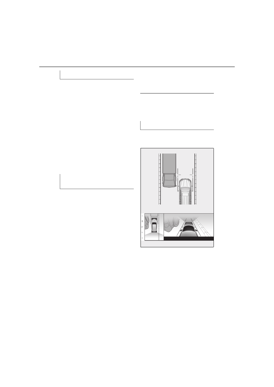
Side Clearance View & panoramic 
view

Check the positions and distance 
between the vehicle width guide line 
and a target object such as the 
obstacle or curb of the road.

Automatic display mode

Automatic display mode of Corner-
ing View

Using the vehicle width guide line

317

4-5. Using the driving support systems

4

Driving

Pull over to the curb as shown in the 
illustration above, taking care not to 
let the vehicle width guide line over-
lap the target object.

Ensure that the vehicle width guide 
line is parallel to the target object.

Cornering View & panoramic view

Check the positions and distance 
between the inner estimated course 
line and a target object such as the 
obstacle or curb of the road.

Take care not to let the estimated 
course line overlap the target 
object.

The rear view & panoramic view/wide rear view & panoramic view screen provide 
support when checking the areas of behind the vehicle and around the vehicle 
while backing up, for example while parking.
The screens will be displayed when the shift lever is in the R position.

Each time the display mode switching button is selected, the mode will change as 
follows:

Using the estimated course line

Checking the rear and around the vehicle

Screen display

318

4-5. Using the driving support systems

Rear view & panoramic view

Intuitive parking assist

When a sensor detects a stationary object, the direction of and the approximate distance to 
the stationary object are displayed and the buzzer sounds.

Rear Cross Traffic Alert/Rear Camera Detection

The indicator is displayed on the screen in the following situations.
• When the rear radar detects an approaching vehicle or obstacle from the rear
• When the rear camera detects a pedestrian to the rear

Rear Camera Detection

Displayed automatically when a pedestrian is detected.

Guide line switching button

Select to switch the guide line mode. (

P.320)

Display mode switching button

Each time the display mode switching button is selected, the mode will change between the 
rear view & panoramic view mode and the wide rear view & panoramic view mode.

Parking Support Brake

When the system determines that the possibility of a collision with detected target objects 
is high, a warning message is displayed.

Setting button

Changes settings, such as the automatically display cornering view, the vehicle body color, 
the intuitive parking assist detection distance. (

P.328)

Intuitive parking assist/Rear Cross Traffic Alert/Rear Camera Detection mute 
button

This button temporarily mutes the intuitive parking assist/Rear Cross Traffic Alert/Rear 
Camera Detection buzzer sound.

A

B

C

D

E

F

G

H

319

4-5. Using the driving support systems

4

Driving

Camera dirt detection icon

This icon is displayed when dirt is detected on the camera.

Wide rear view & panoramic view

Intuitive parking assist

When a sensor detects a stationary object, the direction of and the approximate distance to 
the stationary object are displayed and the buzzer sounds.

Rear Cross Traffic Alert/Rear Camera Detection

The indicator is displayed on the screen in the following situations.
• When the rear radar detects an approaching vehicle or obstacle from the rear
• When the rear camera detects a pedestrian to the rear

Rear Camera Detection

Displayed automatically when a pedestrian is detected.

Guide line switching button

Select to switch the guide line mode. (

P.320)

Display mode switching button

Each time the display mode switching button is selected, the mode will change between the 
rear view & panoramic view mode and the wide rear view & panoramic view mode.

Parking Support Brake

When the system determines that the possibility of a collision with detected target objects 
is high, a warning message is displayed.

Setting button

Changes settings, such as the automatically display cornering view, the vehicle body color, 
the intuitive parking assist detection distance. (

P.328)

Intuitive parking assist/Rear Cross Traffic Alert/Rear Camera Detection mute 

I

A

B

C

D

E

F

G

H

320

4-5. Using the driving support systems

button

This button temporarily mutes the intuitive parking assist/Rear Cross Traffic Alert/Rear 
Camera Detection buzzer sound.

Camera dirt detection icon

This icon is displayed when dirt is detected on the camera.

Rear view & panoramic view/wide rear view & panoramic view display

The monitor is canceled when the shift lever is shifted into any position other than the R 

position.

For details about the intuitive parking assist (

P.261), Rear Cross Traffic Alert function 

(

P.267) and Parking Support Brake function. (

P.275)

The display position of the intuitive parking assist and the position of target objects dis-

played in the camera image do not match.

Each time the guide line switching button is selected, the mode will change as fol-
lows:

Estimated course line

Estimated course lines are displayed which move in accordance with the operation 
of the steering wheel.

WARNING

Intuitive parking assist display

When a sensor indicator on the intuitive parking assist display illuminates in red or a 

buzzer sounds continuously, be sure to check the area around the vehicle immediately 

and do not proceed any further until safety has been ensured, otherwise an unex-

pected accident may occur.

As the intuitive parking assist display and Rear Cross Traffic Alert display are displayed 

over the camera view, it may be difficult to see the intuitive parking assist display and 

Rear Cross Traffic Alert display depending on the color and brightness of the sur-

rounding area.

Guide lines displayed on the screen

I

321

4-5. Using the driving support systems

4

Driving

Distance guide lines

Shows distance in front of the vehicle.
• Display points approximately 3 ft. (1 m) from the edge of the bumper.

Estimated course line

Shows a side estimated course when the steering wheel is turned.

Distance guide lines

Shows the distance behind the vehicle when the steering wheel is turned.
• The guide lines move in conjunction with the estimated course lines.
• The guide lines display points approximately 1.5 ft. (0.5 m) (red) and approximately 3 ft. 

(1 m) (yellow) from the center of the edge of the bumper.

Estimated course line

Shows a rear estimated course when the steering wheel is turned.

Distance guide line

Shows the distance behind the vehicle.
• Displays a point approximately 1.5 ft. (0.5 m) (red

*

) from the edge of the bumper.

Vehicle width guide lines

Displays a guide path when the vehicle is being backed straight up.

Vehicle center guide line

Indicates the estimated vehicle center on the ground.

*

: In estimated course line mode, the line will turn blue.

Parking assist guide line

The steering wheel return points (parking assist guide lines) are displayed.
This mode is recommended for those who are comfortable with parking the vehi-
cle without the aid of the estimated course lines.

Distance guide lines

Shows distance in front of the vehicle.
• Display points approximately 3 ft. (1 m) from the edge of the bumper.

A

B

C

D

E

F

G

A

322

4-5. Using the driving support systems

Distance guide line

Shows the distance behind the vehicle.
• Displays a point approximately 1.5 ft. (0.5 m) (red

*

) from the edge of the bumper.

Vehicle center guide line

Indicates the estimated vehicle center on the ground.

Vehicle width guide lines

Displays a guide path when the vehicle is being backed straight up.

Parking assist guide lines

Shows the path of the smallest turn possible behind the vehicle.

*

: In estimated course line mode, the line will turn blue.

Vehicle center estimated course line

Estimated course lines are displayed which move in accordance with the operation 
of the steering wheel.

Distance guide lines

Shows distance in front of the vehicle.
• Display points approximately 3 ft. (1 m) from the edge of the bumper.

Estimated course line

Shows a side estimated course when the steering wheel is turned.

Distance guide lines

Shows the distance behind the vehicle when the steering wheel is turned.
• The guide lines move in conjunction with the estimated course lines.
• The guide lines display points approximately 1.5 ft. (0.5 m) (red) and approximately 3 ft. 

(1 m) (yellow) from the center of the edge of the bumper.

Estimated course line

Shows a rear estimated course when the steering wheel is turned.

Vehicle center estimated course line

Shows a vehicle center estimated course when the steering wheel is turned.

B

C

D

E

A

B

C

D

E

323

4-5. Using the driving support systems

4

Driving

Distance guide line

Only distance guide line is displayed.
This mode is recommended for those who are comfortable with parking the vehi-
cle without the aid of the guide lines.

Distance guide lines

Shows distance in front of the vehicle.
• Display points approximately 3 ft. (1 m) from the edge of the bumper.

Distance guide line

Shows the distance behind the vehicle.
• Displays a point approximately 1.5 ft. (0.5 m) (red

*

) from the edge of the bumper.

*

: In estimated course line mode, the line will turn blue.

Guide lines display

The display position of the intuitive parking assist and the position of target objects displayed 

in the camera image do not match.

Guide lines

If the back door is not closed, guide lines will not be displayed. If the guide lines do not dis-

play even when the back door is closed, have the vehicle inspected at your Lexus dealer.

WARNING

Guide lines

Depending on the circumstances of the vehicle (number of passengers, amount of lug-

gage, etc.), the position of the guide lines displayed on the screen may change. Be sure 

to check visually around the vehicle before proceeding.

Do not use the system if the display is incorrect due to an uneven (hilly) road or a non-

straight (curvy) road.

A

B

324

4-5. Using the driving support systems

When parking in a space which is in the 
reverse direction to the space 
described in the procedure below, the 
steering directions will be reversed.

1

Shift the shift lever to the R position.

2

Turn the steering wheel so that the 
estimated course lines are within 
the parking space, and back up 
slowly.

Parking space

Estimated course lines

3

When the rear position of the vehi-
cle has entered the parking space, 
turn the steering wheel so that the 
vehicle width guide lines are within 

the left and right dividing lines of 
the parking space.

Vehicle width guide line

4

Once the vehicle width guide lines 
and the parking space lines are 
parallel, straighten the steering 
wheel and back up slowly until the 
vehicle has completely entered the 
parking space.

5

Stop the vehicle in an appropriate 
place, and finish parking.

When parking in a space which is in the 
reverse direction to the space 
described in the procedure below, the 
steering directions will be reversed.

1

Shift the shift lever to the R position.

Parking

Using the estimated course line

A
B

Using parking assist guide line

A

325

4-5. Using the driving support systems

4

Driving

2

Back up until the parking assist 
guide line meets the edge of the 
dividing line of the parking space.

Parking assist guide line

Parking space dividing line

3

Turn the steering wheel all the way 
to the left, and back up slowly.

4

Once the vehicle is parallel with the 
parking space, straighten the steer-
ing wheel and back up slowly until 
the vehicle has completely entered 
the parking space.

5

Stop the vehicle in an appropriate 
place, and finish parking.

When parking in a space which is in the 
reverse direction to the space 
described in the procedure below, the 
steering directions will be reversed.

1

Shift the shift lever to the R position.

2

Turn the steering wheel so that the 
estimated course lines are within 
the parking space, and back up 
slowly.

Parking space

Estimated course lines

3

When the rear position of the vehi-
cle has entered the parking space, 
turn the steering wheel so that the 
vehicle center estimated course 

Using the vehicle center estimated 
course line

A
B

A
B

326

4-5. Using the driving support systems

line is within the center of the park-
ing space.

Vehicle center estimated course 
line

4

Once the vehicle is parallel with the 
parking space, straighten the steer-
ing wheel and back up slowly until 
the vehicle has completely entered 
the parking space.

5

Stop the vehicle in an appropriate 
place, and finish parking.

Even when outside rear view mirrors 
are stored, the monitor can display var-
ious images of the vicinity of the vehicle 
and assist the operation in the confirm-
ing safe conditions in a narrow places, 
parking, etc.

Wide front view & dual side views

Rear view & dual side views

Wide rear view & dual side views

Screen display

For details about the front view and the rear 

view: 

P.310, 317

When folding the outside rear 
view mirrors

A

Screen display

327

4-5. Using the driving support systems

4

Driving

If displayed objects are too small to see 
clearly when the panoramic view is dis-
played, the area around the front side 
or rear side of the vehicle can be mag-
nified.

1

Turn the intuitive parking assist on.

2

Select the area on the panoramic 
view display you wish to magnify.

Selecting one of the 2 areas within 
the dotted lines will magnify that 
area. (Dotted lines are not displayed 
on the actual display.)

To return to the normal view, select 
the panoramic view display again.

Magnifying the display

The magnifying function is enabled when 

all of the following conditions are met:

• The wide front view & panoramic 

view/Side Clearance View & panoramic 

view/rear view & panoramic view/wide 

rear view & panoramic view is displayed.

• The vehicle speed is below approxi-

mately 7 mph (12 km/h).

• The intuitive parking assist is available.

In the following situations, the magnified 

display will be canceled automatically:

• The vehicle speed is approximately 7 

mph (12 km/h) or higher.

• The intuitive parking assist is unavailable.

When the display is magnified, the guide 

lines will not be displayed.

A composite of camera vision cap-
tured in the past from the current vehi-
cle position to assist understanding of 
the situation under the vehicle, tire 
positions, and so on can be displayed. 
The vision is displayed in panoramic 
view, side clearance view, or cornering 
view.

Tire tracks

Displays the tire position guides linked to 
the steering wheel.

Vehicle guide lines

Displays the exterior of the vehicle.

Under vehicle terrain view

Under vehicle terrain view is displayed 

WARNING

Guide lines

When a sensor indicator on the intuitive 

parking assist display illuminates in red or 

a buzzer sounds continuously, be sure to 

check the area around the vehicle imme-

diately and do not proceed any further 

until safety has been ensured, otherwise 

an unexpected accident may occur.

Magnifying function

Magnifying the display

Under vehicle terrain view

A

B

328

4-5. Using the driving support systems

when the setting on the customized set-

ting screen is turned on and the vehicle is 

moving forward or backward.

Under vehicle terrain view is not dis-

played in the following cases:

• The vehicle speed is above 12 mph (20 

km/h).

• The vehicle stops and a certain amount of 

time passes.

• If the vehicle does not move a certain dis-

tance after it is started.

• The side mirrors are folded.

• Multi Terrain ABS is operating.

• The system is not functioning correctly.

The system may not function correctly in 

the following situations:

• Snow covered roads.

• There are shadows from lights and so 

forth.

• There is dirt or a foreign object on the 

camera lens.

• Water (river, sea, etc.).

• Optional equipment has been installed.

• There is an obstacle in front of the cam-

era.

• The tires were replaced.

• The back door is open and the camera is 

not in the correct position.

• The road surface is slippery or the wheels 

slip.

• The vehicle is on a hill or other steep 

roads.

As the vision displayed was captured in 

the past, the screen and the actual situa-

tion may differ in the following cases:

• An obstacle appears or moves after 

vision is captured.

• Sand or snow crumbles and moves after 

vision is captured.

• Mud or puddles are in the display range.

• When the vehicle slips.

Part or all of the under vehicle terrain 

view may appear black in the following 

cases:

• The vehicle starts moving with no cap-

tured vision.

• The steering wheel is turned more than a 

certain angle.

• The vehicle stops and a certain amount of 

time passes.

Settings related to Multi-terrain Moni-
tor such as the cornering view auto dis-
play and vehicle body color can be 
changed.

1

Touch the setting button

2

Select the desired item.

Cornering view

Automatically display the cornering view.

Vehicle Body Color

Change the vehicle body color displayed 
on the screen.

WARNING

Under vehicle terrain view

The tire and vehicle guide lines may 

not align correctly with the actual vehi-

cle position due to the number of pas-

sengers, vehicle load, road gradient, 

road surface conditions, brightness of 

the surroundings, optional equipment, 

tire replacements, and other reasons. 

Always make sure to check your sur-

roundings while you are driving.

Displayed vision is vision that was cap-

tured in the past. Therefore, if obsta-

cles and other objects move after 

being captured, the transparent 

underfloor vision and the actual situa-

tion may not always match.

Changing the Multi-terrain 
Monitor settings

329

4-5. Using the driving support systems

4

Driving

LEXUS Park Assist Distance

Change the distance that the intuitive 
parking assist starts detecting obstacles.

Lexus Park Assist 3D Display

Show or hide the intuitive parking assist 
3D display.

View Under Vehicle

Turn the under vehicle terrain view display 
setting on or off. Setting it to on and mov-
ing the vehicle forward or backwards dis-
plays a composite of camera vision 
captured in the past from the current vehi-
cle position to assist understanding of the 
situation under the vehicle, front tire posi-
tions, and so on. The vision is displayed in 
panoramic view, side clearance view, or 
cornering view.

Suspension of the settings display

For safety purposes, you cannot display the 

custom settings screen while the vehicle is 

moving.

Observe the following precautions. 
Failure to do so may result in an unex-
pected accident. Also, when driving, 
make sure to directly confirm the 
safety of your surroundings and the 
area to the rear of the vehicle.

When using the Multi-terrain 
Monitor

WARNING

Conditions under which the Multi-

terrain Monitor should not be used

Do not use the Multi-terrain Monitor in 

the following situations. The system may 

not operate properly, resulting in an 

unexpected accident.

When driving on an icy, snow-covered 

or otherwise slippery road surface

When using tire chains or a spare tire

When either front door or the back 

door is not completely closed

When driving on an uneven road, such 

as a hill

When tires or suspension parts other 

than those specified are equipped

When the tires are replaced, the posi-

tion indicated by the guide lines dis-

played on the screen may differ.

When any aftermarket parts have 

been installed on the bumper area 

which is displayed by the camera

Guide lines

The tire position indicator lines and vehi-

cle position indicator lines may differ 

from actual vehicle positions depending 

on the number of passengers, cargo 

weight, road grade, road surface condi-

tions, brightness of the surrounding envi-

ronment, etc. Always drive the vehicle 

while confirming the safety of your sur-

roundings.

NOTICE

Panoramic view

In the panoramic view, the system 

combines images taken from the front, 

back, left and right side cameras into a 

single image. There are limits to the 

range and content that can be dis-

played. Understand the characteristics 

of this system before using.

Image clarity may decline at the four 

corners of the panoramic view. How-

ever, this is not a malfunction, as these 

are the regions along the border of 

each camera image where the images 

are combined.

Depending on lighting conditions near 

each of the cameras, bright and dark 

patches may appear on the panoramic 

view.

330

4-5. Using the driving support systems

Area of image of panoramic view:
The Multi-terrain Monitor displays an image of the surrounding view of the vehicle.
Since the panoramic view processes and displays images based on flat road sur-
faces, it cannot depict the position of three-dimension objects (such as vehicle 
bumpers, etc.) that are in positions higher than the surface of the road. Even if there 
is room between the bumpers of the vehicles and it seems not likely to collide in the 
image, in reality, the both vehicles are on a collision course.

NOTICE

The panoramic view display does not 

extend higher than the installation 

position and image capture range of 

each camera.

There are blind spots around the vehi-

cle and there are regions that are not 

displayed in the panoramic view.

Three-dimensional objects displayed 

in wide front view or rear view may not 

be displayed in the panoramic view.

People and other three-dimensional 

obstacles may appear differently when 

displayed in the panoramic view. 

(These differences include, among 

others, cases in which displayed 

objects appear to have fallen over, dis-

appear near image processing areas, 

appear from image processing areas, 

or when the actual distance to an 

object differs from the displayed posi-

tion.)

The panoramic view will not be prop-

erly displayed when either front door 

or the back door is open.

The vehicle icon displayed in the pan-

oramic view is a computer generated 

image, and properties such as the 

color, shape and size will differ from 

the actual vehicle. Therefore, nearby 

three-dimensional objects may appear 

to be touching the vehicle, and actual 

distances to three-dimensional objects 

may differ from those displayed.

Area displayed on screen

331

4-5. Using the driving support systems

4

Driving

Check the safety of the surroundings directly.

The area displayed on the screen

The objects not displayed on the screen

• Objects located in the shaded areas will not be displayed on the screen.

The area displayed on the screen

The parts of objects not displayed on the screen

• Parts of objects which extend above a certain height cannot be displayed on the screen.

Area displayed on screen

As the images obtained from four cam-

eras are processed and displayed on the 

standard of a flat road surface; the pan-

oramic view/moving view/see-through 

view/Side Clearance View/Cornering 

View may be displayed as follows.

• Objects may look collapsed; thinner or 

bigger than usual.

• An object with a higher position than the 

road surface may look farther away than 

it actually is or may not appear at all.

• Tall objects may appear protruding from 

the non-displayed areas of the image.

Variations in the brightness of the image 

A
B

A
B

332

4-5. Using the driving support systems

may appear for every camera.

The displayed image may be shifted by 

inclination of the vehicle body, change in 

vehicle height, etc., depending on the 

number of passengers, amount of lug-

gage, fuel quantity, etc.

If the front doors or back door are not 

completely closed; neither the image nor 

the guide lines are displayed.

The position relations of the vehicle icon 

and the road surface or obstacle may dif-

fer from the actual positions.

The black areas of the vicinity of the vehi-

cle icon are areas that are not captured 

by the camera.

Images like the following are combined, 

thus some areas may be difficult to view.

Wide front view

The area displayed on the screen

The objects not displayed on the 
screen

Area of the image captured by the 
camera

A
B

333

4-5. Using the driving support systems

4

Driving

Side view

The area displayed on the screen

Rear view

The area displayed on the screen

The objects not displayed on the 

screen

Wide rear view

The area displayed on the screen

The objects not displayed on the 
screen

Display range

The area covered by the camera is lim-

ited. Objects which are close to either 

corner of the bumper or under the 

bumper cannot be seen on the screen.

The area displayed on the screen may 

vary depending on vehicle orientation or 

road conditions.

The camera uses a special lens. The dis-

tance in the image displayed on the 

screen will differ from the actual distance.

The cameras for the Multi-terrain 
Monitor are located as shown in the 
illustrations.

A

A
B

The camera

A
B

334

4-5. Using the driving support systems

Front camera

Side cameras

Rear camera

If dirt or foreign matter (such as water 
droplets, snow, mud, etc.) is adhering 
to the camera, it cannot transmit a 
clear image. In this case, flush it with a 
large quantity of water and wipe the 
camera lens clean with a soft and wet 
cloth.
Rear camera: Dirt on the camera lens 

can be cleaned by operating the dedi-
cated camera cleaning washer. 
(

P.211)

Using the camera

NOTICE

How to use the cameras

The Multi-terrain Monitor may not 

operate properly in the following 

cases.

• If the front or the rear of the vehicle or 

the outside rear view mirror has been 

hit, the camera’s position and mount-

ing angle of the camera may change.

• As the camera has a water proof con-

struction, do not detach, disassemble 

or modify it. This may cause incorrect 

operation.

• When cleaning the camera lens, flush 

the camera with a large quantity of 

water and wipe it with a soft and wet 

cloth. Strongly rubbing the camera 

lens may cause the camera lens to be 

scratched and unable to transmit a 

clear image.

• Do not allow organic solvent, car wax, 

window cleaner or glass coat to 

adhere to the camera. If this happens, 

wipe it off as soon as possible.

• If the temperature changes rapidly, 

such as when hot water is poured on 

the vehicle in cold weather, the system 

may not operate normally.

• When washing the vehicle, do not 

apply intensive bursts of water to the 

camera or camera area. Doing so may 

result in the camera malfunctioning.

• When the camera is used under fluo-

rescent lights, sodium light or mercury 

light etc., the lights and the illuminated 

areas may appear to flicker.

• The camera can be damaged by flying 

rocks and other debris.

335

4-5. Using the driving support systems

4

Driving

When cleaning the camera, it may 
be difficult to see the image due to 
the washer fluid. When backing up, 
be sure to visually check all around 
the vehicle both directly and using 
the mirrors before proceeding.

If washer fluid remains on the cam-
era lens surface after cleaning, the 
image may be difficult to see at night 
due to the height or inclination of 
the headlights of the vehicle behind.

Some dirts may not be removed 
completely after cleaning. In this 
case, rinse the camera lens with a 
large quantity of water and then 
wipe it clean with a soft cloth damp-
ened with water.

Washer fluid is sprayed onto the 
camera lens surface. Therefore, the 
ice, snow, etc. adhering around the 
camera cannot be removed.

The parking assist lights of the Multi-
terrain Monitor system are installed in 
the locations shown in the figure.

NOTICE

Do not expose the camera to strong 

impacts as this could cause a malfunc-

tion. If this happens, have the vehicle 

inspected by your Lexus dealer as 

soon as possible.

Cleaning the rear camera with 
washer fluid (rear camera)

NOTICE

Cleaning the camera with washer 

fluid

Do not strike or hit the washer nozzle or 

subject it to a strong impact, as the 

washer nozzle installation position and 

angle may be changed.

Parking assist lights

NOTICE

Parking assist lights

Make sure to observe the following 

precautions, otherwise the Multi-ter-

rain Monitor system may not operate 

correctly:

• Do not apply excessive force to a light 

or subject it to a strong impact. Doing 

so may cause the position or installa-

tion angle of the light to deviate.

• Do not remove, disassemble, or mod-

ify the lights as they have a waterproof 

construction.

• When cleaning the lights, wash them 

with a large amount of water, and then 

wipe them with a soft wet cloth.

• Do not apply organic solvents, waxes, 

oil removing solvents, glass coatings, 

etc. to the covers of the lights, as they 

are made of resin. If such is applied, 

remove it immediately.

• Do not expose the lights to sudden 

temperature changes, such as apply-

ing hot water to them when it is cold.

336

4-5. Using the driving support systems

The distance guide lines and the 
vehicle width guide lines may not 
actually be parallel with the dividing 
lines of the parking space, even 
when they appear to be so. Be sure 
to check visually.

The distances between the vehicle 
width guide lines and the left and 
right dividing lines of the parking 
space may not be equal, even when 
they appear to be so. Be sure to 
check visually.

The distance guide lines give a dis-
tance guide for flat road surfaces. In 
any of the following situations, there 
is a margin of error between the 
guide lines on the screen and the 
actual distance/course on the road.

The distance guide lines will appear to 
be closer to the vehicle than the actual 
distance. Because of this, objects will 
appear to be farther away than they 

actually are. In the same way, there will 
be a margin of error between the guide 
lines and the actual distance/course on 
the road.

The distance guide lines will appear to 
be farther from the vehicle than the 
actual distance. Because of this, 
objects will appear to be closer than 
they actually are. In the same way, 
there will be a margin of error between 
the guide lines and the actual dis-
tance/course on the road.

NOTICE

• When washing the vehicle with a high-

pressure washer, do not spray water 

directly on the lights or their surround-

ing area. High-pressure water can 

damage the lights and cause them to 

not operate correctly.

If a light has been subjected to a strong 

impact, it may be damaged. Have the 

vehicle inspected by your Lexus 

dealer as soon as possible.

Difference between the screen 
and the actual road

When the ground behind the vehicle 
slopes up sharply

When the ground behind the vehicle 
slopes down sharply

337

4-5. Using the driving support systems

4

Driving

When any part of the vehicle sags due 
to the number of passengers or the dis-
tribution of the load, there is a margin 
of error between the guide lines on the 
screen and the actual distance/course 
on the road.

A margin of error

As the guide lines are shown in the air 
near the rear bumper, there are times 
that they may look like they are off-
center.

When there are three-dimensional objects (such as vehicle bumpers, etc.) nearby 
in positions higher than the surface of the road, take extra care when using the fol-
lowing.

When any part of the vehicle sags

Vehicle center estimated course 
line

A

Distortion of three-dimensional objects on the screen

WARNING

Intuitive parking assist pop-up display

When a sensor indicator on the intuitive parking assist display illuminates in red or a 

buzzer sounds continuously, be sure to check the area around the vehicle immediately 

and do not proceed any further until safety has been ensured, otherwise an unexpected 

accident may occur.

338

4-5. Using the driving support systems

Since the panoramic view, Side Clearance View and Cornering View process and 
display images based on flat road surfaces, it cannot depict the position of three-
dimension objects (such as vehicle bumpers, etc.) that are in positions higher than 
the surface of the road. For example, even though it appears that there is space 
between the bumpers of the two vehicles in the illustration below and they are not 
likely to collide, in reality, a collision is about to occur.

Since the estimated course line is dis-
played for a flat road surface, it cannot 
depict the position of three-dimen-
sional objects (such as vehicle bum-
pers, etc.) that are in positions higher 
than the surface of the road. Even if the 
bumper of the vehicle is on the outside 
of the estimated course line in the 
image, in reality, the vehicles are on a 
collision course.

Estimated course line

Panoramic view display (including magnified display), Side Clearance View 
and Cornering View display

Estimated course lines

A

339

4-5. Using the driving support systems

4

Driving

Three-dimensional objects (such as the 
overhang of a wall or loading platform 
of a truck) in high positions may not be 
projected on the screen. Check the 
safety of the surroundings directly.

Visually check the surroundings and 
the area behind the vehicle. In the case 
shown below, the truck appears to be 
outside of the estimated course lines 
and the vehicle does not look as if it hits 
the truck. However, the rear body of 
the truck may actually cross over the 
estimated course lines. In reality if you 
back up as guided by the estimated 
course lines, the vehicle may hit the 
truck.

Estimated course lines

Visually check the surroundings and 
the area behind the vehicle. On the 
screen, it appears that a truck is park-
ing at point 

. However, in reality if 

you back up to point 

, you will hit 

the truck. On the screen, it appears 
that 

 is closest and 

 is farthest 

away. However, in reality, the distance 
to 

 and 

 is the same, and 

 is 

farther than 

 and 

.

Distance guide lines

A

B

A

A

C

A

C

B

A

C

340

4-5. Using the driving support systems

In panoramic view, a diagonal beam 
may appear straight and seems likely 
not to be struck, however, since the top 
part of the beam is actually overhang-
ing, the vehicle may hit it. Make sure to 
visually check the rear and surround-
ings.

Unlike the normal panoramic view, the 
panoramic view magnifying function 
zooms in on the vehicle icon. There-
fore, white lines on the road, walls, and 
other objects may look bent.

Overhang of a diagonal beam

Magnifying function

341

4-5. Using the driving support systems

4

Driving

The tire position indicator lines and 
vehicle position indicator lines may dif-
fer from actual vehicle positions 
depending on the number of passen-
gers, weight of the load, road grade, 
road surface conditions, brightness of 
the surrounding environment, etc. 
Always drive the vehicle while directly 
confirming the safety of your surround-
ings

Using under vehicle terrain view

The images displayed were previously 

taken behind the current vehicle position.

Therefore, actual conditions may differ 

from those shown on the screen in the 

following situations.

• When conditions changed such as when 

an object moved or entered the frame 

after the image was taken.

• Loose material like sand or snow has 

crumbled or shifted

• An obstacle has moved

• There is a puddle, tract of mud, etc., 

within the display range

• The vehicle slips

In the following situations, actual tire 

positions and vehicle position may differ 

from those indicated by the tire position 

indicator lines and vehicle position indi-

cator lines.

• Tires have been replaced

• Optional equipment has been installed

If you notice any of the following symptoms, refer to the likely cause and the solu-
tion, and re-check.
If the symptom is not resolved by the solution, have the vehicle inspected by your 
Lexus dealer.

Under vehicle terrain view

WARNING

Guide lines

The displayed guide lines are composed 

with the image that was previously taken 

and may differ from the actual state. 

Always drive the vehicle while confirm-

ing the safety of your surroundings.

Things you should know

If you notice any symptoms

342

4-5. Using the driving support systems

Symptom

Likely cause

Solution

The image is difficult to see

The vehicle is in a dark 
area

The temperature around 
the lens is either high or 
low

The outside temperature is 
low

There are water droplets 
on the camera

It is raining or humid

Foreign matter (mud, etc.) 
is adhering to the camera

Sunlight or headlights are 
shining directly into the 
camera

The vehicle is under fluo-
rescent lights, sodium 
lights, mercury lights, etc.

Back up while visually check-
ing the vehicle’s surround-
ings. (Use the monitor again 
once conditions have been 
improved.)
The procedure for adjusting 
the picture quality of the 
Multi-terrain Monitor sys-
tem is the same as the proce-
dure for adjusting the screen 
display. Refer to the “MULTI-
MEDIA OWNER’S MAN-
UAL”.

The image is blurry

Dirt or foreign matter (such 
as water droplets, snow, 
mud, etc.) is adhering to the 
camera.

Flush the camera with a large 
quantity of water and wipe 
the camera lens clean with a 
soft and wet cloth.
Rear camera: Operate the 
dedicated camera cleaning 
washer and clean the camera 
lens. (

P.211)

The image is out of alignment

The camera or surrounding 
area has received a strong 
impact.

Have the vehicle inspected 
by your Lexus dealer.

The guide lines are very far 
out of alignment

The camera position is out of 
alignment.

Have the vehicle inspected 
by your Lexus dealer.

The vehicle is tilted. (There 
is a heavy load on the vehi-
cle, tire pressure is low due 
to a tire puncture, etc.)

The vehicle is used on an 
incline.

If this happens due to these 
causes, it does not indicate a 
malfunction.
Back up while visually check-
ing the vehicle’s surround-
ings.

The estimated course lines 
move even though the steer-
ing wheel is straight

There is a malfunction in the 
signals being output by the 
steering sensor.

Have the vehicle inspected 
by your Lexus dealer.

343

4-5. Using the driving support systems

4

Driving

Guide lines are not displayed The back door is open.

Close the back door.
If this does not resolve the 
symptom, have the vehicle 
inspected by your Lexus 
dealer.

The panoramic view display 
cannot be magnified

The intuitive parking assist 
may be malfunctioning or 
dirty.

Follow the correction proce-
dures for malfunctions of the 
intuitive parking assist. 
(

P.261)

The See-through view/Mov-
ing view/Side Clearance 
View/Cornering View can-
not be displayed

 is displayed

When dirt is detected on the 
camera.

Clean any dirt from the cam-
era for which the icon was 
displayed.
Operate the dedicated cam-
era cleaning washer and 
clean the camera lens. 
(

P.211)

Product license

Symptom

Likely cause

Solution

344

4-5. Using the driving support systems

Multi-information display (

P.82)

MODE SELECT switch

DRIVE MODE switch

1

Press the DRIVE MODE switch.

The indicator 

 on the switch will turn on.

2

Select the driving modes on the 
multi-information display while 

turning the MODE SELECT switch 
left and right.

Vehicles without Adaptive Variable 
Suspension system

• Normal mode

Provides an optimal balance of fuel econ-
omy, quietness, and dynamic performance. 
Suitable for city driving.

• Eco drive mode

Helps the driver accelerate in an eco-
friendly manner and improve fuel economy 
through moderate throttle characteristics 
and by controlling the operation of the air 
conditioning system (heating/cooling). The 
Eco drive mode indicator comes on.

• Sport  mode

Assists acceleration response by con-
trolling the transmission, engine and steer-
ing. Suitable for when precise handling is 
desirable, for example when driving on 
mountain roads. The sport mode indicator 
comes on.

Driving mode select switch

The driving modes can be selected 
to suit driving condition.

System components

Selecting the driving mode

A
B
C

A

345

4-5. Using the driving support systems

4

Driving

Vehicles with Adaptive Variable 
Suspension system

• Normal mode

Provides an optimal balance of fuel econ-
omy, quietness, and dynamic performance. 
Suitable for city driving.

• Comfort  mode

By controlling the suspension, riding com-
fort is further enhanced. Suitable for city 
driving. The comfort mode indicator 
comes on.

• Eco drive mode

Helps the driver accelerate in an eco-
friendly manner and improve fuel economy 
through moderate throttle characteristics 
and by controlling the operation of the air 
conditioning system (heating/cooling). The 
Eco drive mode indicator comes on.

• SPORT  S  mode

Assists acceleration response by con-
trolling the transmission. This mode is suit-
able for when powerful acceleration is 
desired. The SPORT S mode indicator 
comes on.

• SPORT  S+  mode

Helps to ensure the controllability and sta-
bility of the vehicle by integrally controlling 
the steering wheel and suspensions as well 
as the transmission and engine, making it 
suitable for sporty driving. The SPORT S+ 
mode indicator comes on.

• Custom mode

Allows you to drive with the power train, 
steering wheel, suspensions and air condi-
tioning system functions set to your pre-
ferred settings. Custom mode settings can 
only be changed on the drive mode cus-
tomization display of Multimedia Display. 
(

P.552) The custom mode indicator 

comes on.

The driving mode select switch can be 

operated when

The four-wheel drive control switch is in 

H4.

Operation of the air conditioning sys-

tem in Eco drive mode

Eco drive mode controls the heating/cool-

ing operations and fan speed of the air con-

ditioning system to enhance fuel efficiency. 

To improve air conditioning performance, 

perform the following operations:
• Turn off eco air conditioning mode 

(

P.388)

• Adjust the fan speed (

P.387)

• Turn  off  Eco  drive  mode  (

P.344)

Automatic deactivation of driving mode

Driving mode is deactivated and the driving 

mode will be changed to normal mode in 

the following conditions:

When SPORT S mode, SPORT S+ mode 

or custom mode is selected

After turning the engine switch off and 

then turning it to ON.

When the four-wheel drive control 

switch is in L4

When the Multi-terrain Select is turned 

on

346

4-5. Using the driving support systems

When Eco drive mode or comfort mode 

is selected

When the four-wheel drive control 

switch is in L4

When the Multi-terrain Select is turned 

on

Customization (vehicles with Adaptive 

Variable Suspension system)

The Custom mode can be changed.
(Customizable features: 

P.565)

*

: If equipped

Height select switches

Higher

Lower

Meter display

AHC display

When the vehicle is stopped, selected 
vehicle height mode is displayed. When 
driving, current vehicle height mode is dis-
played.

Easy access mode indicator

AHC (Active Height Control 
Suspension)

*

The vehicle height modes can be 
selected to suit driving condition.

System components

A
B

A

B

347

4-5. Using the driving support systems

4

Driving

Front Multi Operation Panel

Vehicle height mode

Selected vehicle height mode is displayed.

AHC display

When the vehicle is stopped, selected 
vehicle height mode is displayed. When 
driving, current vehicle height mode is dis-
played.

Easy access mode switch

Height control OFF switch

Press the height select switch.

Selected vehicle height mode is displayed 
on the AHC display and Front Multi Oper-
ation Panel. At this time, a part of the AHC 
display will flash. After the vehicle height is 
changed, the display will stop flashing, and 
come on.

N (Normal) mode

H1 (Hi1) mode

H2 (Hi2) mode

L (Lo) mode

The vehicle height modes will change 
as the following table by operating the 
height select switch.

N mode

The standard vehicle height. This mode 
is suitable for ordinary driving.

Selecting vehicle height

A

B

C
D

Vehicle height modes

Vehicle 

height 

modes

Height select switch

H2

H1

H2

H1

N

H2

N

L

H1

L

L

N

A
B
C
D


Content      ..     8      9      10      11     ..