Lexus RC F (2022 year). Manual in english - page 10
 

  Index      Manuals     Lexus RC F (2022 year). Manual in english


Search            copyright infringement  


Content      ..     8      9      10      11     ..


Lexus RC F (2022 year). Manual in english - page 10


167

4-5. Using the driving support systems

4

Driving

Lane departure alert function is operating.

Operation display of steering 
wheel operation support

Indicates that steering wheel assistance of 
the steering control function is operating.

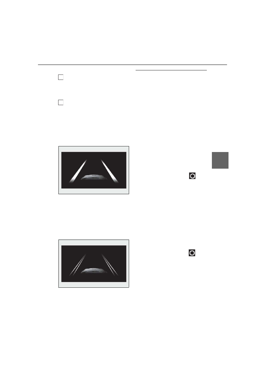
Lane departure alert function dis-
play

Displayed when the multi-information dis-
play is switched to the driving assist system 
information screen.

Inside of displayed white lines is 
white

Indicates that the system is recognizing 
white (yellow) lines. When the vehicle 
departs from its lane, the white line dis-
played on the side the vehicle departs from 
flashes orange.

Inside of displayed white lines is 
black

Indicates that the system is not able to rec-
ognize white (yellow) lines or is temporar-
ily canceled.

Operation conditions of each function

Lane departure alert function

This function operates when all of the fol-

lowing conditions are met.

• LDA is turned on.

• Vehicle speed is approximately 32 mph 

(50 km/h) or more.

• System recognizes white (yellow) lines.

• Width of traffic lane is approximately 9.8 

ft. (3 m) or more.

• Turn signal lever is not operated.

• Vehicle is driven on a straight road or 

around a gentle curve with a radius of 

more than approximately 492 ft. (150 m).

• No system malfunctions are detected. 

(

P.169)

Steering control function

This function operates when all of the fol-

lowing conditions are met in addition to the 

operation conditions for the lane depar-

ture alert function.
• Setting for “Steering Assist” in 

 of the 

multi-information display is set to “On”. 

(

P.73)

• Vehicle is not accelerated or decelerated 

by a certain amount or more.

• Steering wheel is not operated with a 

steering force level suitable for changing 

lanes.

• ABS, VSC, TRAC and PCS are not oper-

ating.

• TRAC or VSC is not turned off.

• Hands off steering wheel warning is not 

displayed. (

P.168)

Vehicle sway warning function

This function operates when all of the fol-

lowing conditions are met.
• Setting for “Sway Warning” in 

 of the 

multi-information display is set to “On”. 

(

P.73)

• Vehicle speed is approximately 32 mph 

(50 km/h) or more.

• Width of traffic lane is approximately 9.8 

ft. (3 m) or more.

• No system malfunctions are detected. 

(

P.169)

Temporary cancellation of functions

When the operation conditions are no lon-

ger met, a function may be temporarily can-

B

C

168

4-5. Using the driving support systems

celed. However, when the operation 

conditions are met again, operation of the 

function is automatically restored. (

P.167)

Steering control function

Depending on the vehicle speed, lane 

departure situation, road conditions, etc., 

the driver may not feel the function is oper-

ating or the function may not operate at all.

Lane departure alert function

The warning buzzer may be difficult to hear 

due to external noise, audio playback, etc. 

Also, it may be difficult to feel steering 

wheel vibrations due to the road conditions 

etc.

Hands off steering wheel warning

In the following situations, a warning mes-

sage urging the driver to hold the steering 

wheel and the symbol shown in the illustra-

tion are displayed on the multi-information 

display to warn the driver.The warning stops 

when the system determines that the driver 

holds the steering wheel. Always keep your 

hands on the steering wheel when using this 

system, regardless of warnings.

When the system determines that the 

driver is driving without holding the steer-

ing wheel while the system is operating

If the driver continues to keep their hands 
off of the steering wheel, the buzzer 
sounds, the driver is warned and the func-
tion is temporarily canceled. This warning 
also operates in the same way when the 
driver continuously operates the steering 
wheel only a small amount.
The buzzer also sounds even if the alert 
type is set to 

.

Depending on the vehicle condition and 
road conditions, the warning may not 

operate. Also, if the system determines that 
the vehicle is driving around a curve, warn-
ings will occur earlier than during 
straight-lane driving.

When the system determines that the 

driver is driving without holding the steer-

ing wheel while the steering wheel assist 

of the steering assist function is operat-

ing.

If the driver continues to keep their hands 
off of the steering wheel and the steering 
wheel assist is operating, the buzzer 
sounds and the driver is warned. Each time 
the buzzer sounds, the continuing time of 
the buzzer becomes longer.
The buzzer also sounds even if the alert 
type is set to 

.

Vehicle sway warning function

When the system determines that the vehi-

cle is swaying while the vehicle sway warn-

ing function is operating, a buzzer sounds 

and a warning message urging the driver to 

rest and the symbol shown in the illustration 

are simultaneously displayed on the 

multi-information display.

Depending on the vehicle and road condi-

tions, the warning may not operate.

White (yellow) lines are only on one side 

of road

The LDA system will not operate for the 

side on which white (yellow) lines could not 

be recognized.

Conditions in which functions may not 

operate properly

In the following situations, the camera sen-

sor may not detect white (yellow) lines and 

various functions may not operate normally.

169

4-5. Using the driving support systems

4

Driving

There are shadows on the road that run 

parallel with, or cover, the white (yellow) 

lines.

The vehicle is driven in an area without 

white (yellow) lines, such as in front of a 

tollgate or checkpoint, or at an intersec-

tion, etc.

The white (yellow) lines are cracked, 

“Botts’ dots”, “Raised pavement marker” 

or stones are present.

The white (yellow) lines cannot be seen 

or are difficult to see due to sand, etc.

The vehicle is driven on a road surface 

that is wet due to rain, puddles, etc.

The traffic lines are yellow (which may be 

more difficult to recognize than lines that 

are white).

The white (yellow) lines cross over a curb, 

etc.

The vehicle is driven on a bright surface, 

such as concrete.

The vehicle is driven on a surface that is 

bright due to reflected light, etc.

The vehicle is driven in an area where the 

brightness changes suddenly, such as at 

the entrances and exits of tunnels, etc.

Light from the headlights of an oncoming 

vehicle, the sun, etc. enters the camera.

The vehicle is driven where the road 

diverges, merges, etc.

The vehicle is driven on a slope.

The vehicle is driven on a road which tilts 

left or right, or a winding road.

The vehicle is driven on an unpaved or 

rough road.

The vehicle is driven around a sharp 

curve.

The traffic lane is excessively narrow or 

wide.

The vehicle is extremely tilted due to car-

rying heavy luggage or having improper 

tire pressure.

The distance to the preceding vehicle is 

extremely short.

The vehicle is moving up and down a 

large amount due to road conditions 

during driving (poor roads or road 

seams).

The headlight lenses are dirty and emit a 

faint amount of light at night, or the beam 

axis has deviated.

The vehicle is struck by a crosswind.

The vehicle has just changed lanes or 

crossed an intersection.

Snow tires, etc. are equipped.

Warning message

If the following warning message is dis-

played on the multi-information display and 

the LDA indicator illuminates in orange, fol-

low the appropriate troubleshooting proce-

dure.

Warning mes-
sage

Details/Actions

“Lane Depar-
ture Alert 
Malfunction 
Visit Your 
Dealer”

The system may not be 
operating properly.

Have the vehicle 

inspected at your Lexus 
dealer.

“Front Cam-
era Unavail-
able Remove 
Debris On 
Windshield”

Dirt, rain, condensation, 
ice, snow, etc. are present 
on the windshield in front 
of the camera sensor.

Turn the LDA system off, 

remove any dirt, rain, con-
densation, ice, snow, etc. 
from the windshield, and 
then turn the LDA system 
back on.

170

4-5. Using the driving support systems

If a different warning message is displayed, 

follow the instructions displayed on the 

screen.

Customization

The following settings can be changed.

For how to change settings, refer to P.358

“Front Cam-
era Unavail-
able”

The operation conditions 
of the camera sensor (tem-
perature, etc.) are not met.

When the operation 

conditions of the camera 
sensor (temperature, etc.) 
are met, the LDA system 
will become available. Turn 
the LDA system off, wait 
for a little while, and then 
turn the LDA system back 
on.

“Lane Depar-
ture Alert 
Unavailable”

The LDA system is tempo-
rarily canceled due to a 
malfunction in a sensor 
other than the camera sen-
sor.

Turn the LDA system off 

and follow the appropriate 
troubleshooting proce-
dures for the warning mes-
sage. Afterward, drive the 
vehicle for a short time, 
and then turn the LDA sys-
tem back on.

“Lane Depar-
ture Alert 
Unavailable 
Below 
Approx 
32MPH”

The LDA system cannot be 
used as the vehicle speed 
is less than approximately 
32 mph (50 km/h).

Drive the vehicle at 

approximately 32 mph 
(50 km/h) or more.

“Lane Depar-
ture Alert 
Unavailable at 
Current 
Speed”

The LDA system cannot be 
used as the vehicle speed 
is too high.

Slow down.

Warning mes-
sage

Details/Actions

Function

Setting details

Lane departure 
alert function

Adjust alert sensitivity

Adjust alert type

Steering control 
function

Turn steering wheel 
assistance on and off

Vehicle sway 
warning function

Turn function on and 
off

Adjust alert sensitivity

171

4-5. Using the driving support systems

4

Driving

Vehicle-to-vehicle distance switch
Display
Set speed
Indicators

Cruise control switch

Dynamic radar cruise con-
trol

In vehicle-to-vehicle distance con-
trol mode, the vehicle automati-
cally accelerates and decelerates 
to match the speed changes of the 
preceding vehicle even if the accel-
erator pedal is not depressed. In 
constant speed control mode, the 
vehicle runs at a fixed speed.

Use the dynamic radar cruise con-
trol on freeways and highways.

Vehicle-to-vehicle distance con-
trol mode (

P.173)

Constant speed control mode 
(

P.176)

System Components

A

B

C

D

WARNING

Before using dynamic radar cruise 

control

Driving safely is the sole responsibility 

of the driver. Do not rely solely on the 

system, and drive safely by always pay-

ing careful attention to your surround-

ings.

The dynamic radar cruise control pro-

vides driving assistance to reduce the 

driver’s burden. However, there are 

limitations to the assistance provided.

Read the following conditions care-

fully. Do not overly rely on this system 

and always drive carefully.

• When the sensor ma

y not be correctly 

detecting the vehicle ahead: 

P.178

• Conditions under which the vehi-

cle-to-vehicle distance control mode 

may not function correctly: 

P.178

Set the speed appropriately depend-

ing on the speed limit, traffic flow, road 

conditions, weather conditions, etc. 

The driver is responsible for checking 

the set speed.

Even when the system is functioning 

normally, the condition of the preced-

ing vehicle as detected by the system 

may differ from the condition 

observed by the driver. Therefore, the 

driver must always remain alert, assess 

the danger of each situation and drive 

safely. Relying on this system or assum-

ing the system ensures safety while 

driving can lead to an accident, result-

ing in death or serious injury.

Switch the dynamic radar cruise con-

trol off using the “ON/OFF” button 

when not in use.

E

172

4-5. Using the driving support systems

WARNING

Cautions regarding the driving assist 

systems

Observe the following precautions, as 

there are limitations to the assistance 

provided by the system.

Failure to do so may cause an accident 

resulting in death or serious injury.

Assisting the driver to measure follow-

ing distance

The dynamic radar cruise control is only 

intended to help the driver in determin-

ing the following distance between the 

driver’s own vehicle and a designated 

vehicle traveling ahead. It is not a mecha-

nism that allows careless or inattentive 

driving, and it is not a system that can 

assist the driver in low-visibility condi-

tions. It is still necessary for driver to pay 

close attention to the vehicle’s surround-

ings.

Assisting the driver to judge proper 

following distance

The dynamic radar cruise control deter-

mines whether the following distance 

between the driver’s own vehicle and a 

designated vehicle traveling ahead is 

within a set range. It is not capable of 

making any other type of judgement. 

Therefore, it is absolutely necessary for 

the driver to remain vigilant and to deter-

mine whether or not there is a possibility 

of danger in any given situation.

Assisting the driver to operate the 

vehicle

The dynamic radar cruise control has 

limited capability to prevent or avoid a 

collision with a vehicle traveling ahead. 

Therefore, if there is ever any danger, the 

driver must take immediate and direct 

control of the vehicle and act appropri-

ately in order to ensure the safety of all 

involved.

Situations unsuitable for dynamic 

radar cruise control

Do not use dynamic radar cruise control 

in any of the following situations.

Doing so may result in inappropriate 

speed control and could cause an acci-

dent resulting in death or serious injury.

Roads where there are pedestrians, 

cyclists, etc.

In heavy traffic

On roads with sharp bends

On winding roads

On slippery roads, such as those cov-

ered with rain, ice or snow

On steep downhills, or where there 

are sudden changes between sharp up 

and down gradients

Vehicle speed may exceed the set 

speed when driving down a steep hill.

At entrances to freeways and highways

When weather conditions are bad 

enough that they may prevent the sen-

sors from detecting correctly (fog, 

snow, sandstorm, heavy rain, etc.)

When there is rain, snow, etc. on the 

front surface of the radar sensor or 

camera sensor

In traffic conditions that require fre-

quent repeated acceleration and 

deceleration

During emergency towing

When an approach warning buzzer is 

heard often

173

4-5. Using the driving support systems

4

Driving

This mode employs a radar sensor to detect the presence of vehicles up to approx-
imately 328 ft. (100 m) ahead, determines the current vehicle-to-vehicle following 
distance, and operates to maintain a suitable following distance from the vehicle 
ahead.

Note that vehicle-to-vehicle distance will close in when traveling on downhill slopes.

Example of constant speed cruising
When there are no vehicles ahead

The vehicle travels at the speed set by the driver. The desired vehicle-to-vehicle distance 
can also be set by operating the vehicle-to-vehicle distance switch.

Example of deceleration cruising and follow-up cruising
When a preceding vehicle driving slower than the set speed appears

When a vehicle is detected running ahead of you, the system automatically decelerates 
your vehicle. When a greater reduction in vehicle speed is necessary, the system applies 
the brakes (the stop lights will come on at this time). The system will respond to changes in 
the speed of the vehicle ahead in order to maintain the vehicle-to-vehicle distance set by 
the driver. Approach warning warns you when the system cannot decelerate sufficiently to 
prevent your vehicle from closing in on the vehicle ahead.

Example of acceleration 
When there are no longer any preceding vehicles driving slower than the set 
speed

The system accelerates until the set speed is reached. The system then returns to constant 
speed cruising.

Driving in vehicle-to-vehicle distance control mode

A

B

C

174

4-5. Using the driving support systems

1

Press the “ON/OFF” button to acti-
vate the cruise control.

Radar cruise control indicator will come on 

and a message will be displayed on the 

multi-information display.
Press the button again to deactivate the 

cruise control.
If the “ON/OFF” button is pressed and 

held for 1.5 seconds or more, the system 

turns on in constant speed control mode. 

(

P.176)

2

Accelerate or decelerate, with 
accelerator pedal operation, to the 
desired vehicle speed (at or above 
approximately 30 mph [50 km/h]) 
and push the lever down to set the 
speed.

Cruise control “SET” indicator will come 

on.
The vehicle speed at the moment the lever 

is released becomes the set speed.

To change the set speed, operate the 
lever until the desired set speed is dis-
played.

1

Increases the speed

2

Decreases the speed

Fine adjustment: Momentarily move 
the lever in the desired direction.
Large adjustment: Hold the lever up or 
down to change the speed, and release 
when the desired speed is reached.
In the vehicle-to-vehicle distance con-
trol mode, the set speed will be 
increased or decreased as follows:

For the U.S. mainland and Hawaii

Fine adjustment: By 1 mph (1.6 km/h)

*1

 or 1 

km/h (0.6 mph)

*2

 each time the lever is 

operated

Setting the vehicle speed (vehi-
cle-to-vehicle distance control 
mode)

Adjusting the set speed

175

4-5. Using the driving support systems

4

Driving

Large adjustment: Increases or decreases 
in 1 mph (1.6 km/h)

*1

 or 1 km/h (0.6 mph)

*2


increments for as long as the lever is held

For Canada, Guam and Puerto 
Rico

Fine adjustment: By 1 mph (1.6 km/h)

*1

 or 1 

km/h (0.6 mph)

*2

 each time the lever is 

operated
Large adjustment: Increases or decreases 
in 5 mph (8 km/h)

*1

 or 5 km/h (3.1 mph)

*2


increments for as long as the lever is held

In the constant speed control mode 
(

P.176), the set speed will be 

increased or decreased as follows:

Fine adjustment: By 1 mph (1.6 km/h)

*1

 or 

1.6 km/h (1 mph)

*2

 each time the lever is 

operated
Large adjustment: The speed will continue 
to change while the lever is held.

*1

: When the set speed is shown in “MPH”

*2

: When the set speed is shown in “km/h”

Pressing the switch changes the vehi-
cle-to-vehicle distance as follows:

1

Long

2

Medium

3

Short

The vehicle-to-vehicle distance is set auto-
matically to long mode when the engine 
switch is turned to IGNITION ON mode.
If a vehicle is running ahead of you, the pre-
ceding vehicle mark 

 will also be dis-

played.

Select a distance from the table below. 
Note that the distances shown corre-
spond to a vehicle speed of 50 mph 
(80 km/h). Vehicle-to-vehicle distance 
increases/decreases in accordance 
with vehicle speed.

Changing the vehicle-to-vehicle 
distance (vehicle-to-vehicle dis-
tance control mode)

Vehicle-to-vehicle distance set-
tings (vehicle-to-vehicle dis-
tance control mode)

Distance 

options

Vehicle-to-vehicle dis-

tance

Long

Approximately 160 ft. (50 
m)

Medium

Approximately 130 ft. (40 
m)

Short

Approximately 100 ft. (30 
m)

A

176

4-5. Using the driving support systems

1

Pulling the lever toward you can-
cels the speed control.

The speed control is also canceled when 
the brake pedal is depressed.

2

Pushing the lever up resumes the 
cruise control and returns vehicle 
speed to the set speed.

However, cruise control does not resume 
when the vehicle speed is approximately 
25 mph (40 km/h) or less.

When your vehicle is too close to a 
vehicle ahead, and sufficient automatic 
deceleration via the cruise control is 
not possible, the display will flash and 
the buzzer will sound to alert the driver. 
An example of this would be if another 
driver cuts in front of you while you are 
following a vehicle. Depress the brake 
pedal to ensure an appropriate vehi-
cle-to-vehicle distance.

Warnings may not occur when

In the following instances, warnings 
may not occur even when the vehi-
cle-to-vehicle distance is small.

When the speed of the preceding 
vehicle matches or exceeds your 
vehicle speed

When the preceding vehicle is trav-
eling at an extremely slow speed

Immediately after the cruise control 
speed was set

When depressing the accelerator 
pedal

When constant speed control mode is 
selected, your vehicle will maintain a 
set speed without controlling the vehi-
cle-to-vehicle distance. Select this 
mode only when vehicle-to-vehicle dis-
tance control mode does not function 
correctly due to a dirty radar sensor, 
etc.

1

With the cruise control off, press 
and hold the “ON/OFF” button for 
1.5 seconds or more.

Immediately after the “ON/OFF” button is 

pressed, the radar cruise control indicator 

Canceling and resuming the 
speed control

Approach warning (vehi-
cle-to-vehicle distance control 
mode)

Selecting constant speed con-
trol mode

177

4-5. Using the driving support systems

4

Driving

will come on. Afterwards, it switches to the 

cruise control indicator.
Switching to constant speed control mode 

is only possible when operating the lever 

with the cruise control off.

2

Accelerate or decelerate, with 
accelerator pedal operation, to the 
desired vehicle speed (at or above 
approximately 30 mph [50 km/h]) 
and push the lever down to set the 
speed.

Cruise control “SET” indicator will come 

on.
The vehicle speed at the moment the lever 

is released becomes the set speed.
Adjusting the speed setting: 

P.174

Canceling and resuming the speed setting: 

P.176

Dynamic radar cruise control can be set 

when

The shift lever is in D.

Range 4 or higher of D has been selected 

by using the paddle shift switch.

Vehicle speed is at or above approxi-

mately 30 mph (50 km/h).

Accelerating after setting the vehicle 

speed

The vehicle can accelerate by operating the 

accelerator pedal. After accelerating, the 

set speed resumes. However, during vehi-

cle-to-vehicle distance control mode, the 

vehicle speed may decrease below the set 

speed in order to maintain the distance to 

the preceding vehicle.

Automatic cancelation of vehi-

cle-to-vehicle distance control mode

Vehicle-to-vehicle distance control mode is 

automatically canceled in the following situ-

ations:

Actual vehicle speed falls at or below 

approximately 25 mph (40 km/h).

VSC is activated.

TRAC is activated for a period of time.

When the VSC or TRAC system is 

turned off.

The sensor cannot detect correctly 

because it is covered in some way.

Pre-collision braking is activated.

If vehicle-to-vehicle distance control mode 

is automatically canceled for any other 

reason, there may be a malfunction in the 

system. Contact your Lexus dealer.

Automatic cancelation of constant 

speed control mode

Constant speed control mode is automati-

cally canceled in the following situations:

Actual vehicle speed is more than 

approximately 10 mph (16 km/h) below 

the set vehicle speed.

Actual vehicle speed falls below approxi-

mately 25 mph (40 km/h).

VSC is activated.

TRAC is activated for a period of time.

When the VSC or TRAC system is 

turned off.

Pre-collision braking is activated.

If constant speed control mode is automati-

cally canceled for any other reason, there 

may be a malfunction in the system. Con-

tact your Lexus dealer.

178

4-5. Using the driving support systems

Brake system operation sound

If the brakes are applied automatically while 

the vehicle is in vehicle-to-vehicle distance 

control mode, a brake system operation 

sound may be heard. This does not indicate 

a malfunction.

Warning messages and buzzers for 

dynamic radar cruise control

Warning messages and buzzers are used to 

indicate a system malfunction or to inform 

the driver of the need for caution while driv-

ing. If a warning message is shown on the 

multi-information display, read the message 

and follow the instructions.

When the sensor may not be correctly 

detecting the vehicle ahead

In the case of the following and depending 

on the conditions, operate the brake pedal 

when deceleration of the system is insuffi-

cient or operate the accelerator pedal 

when acceleration is required.

As the sensor may not be able to correctly 

detect these types of vehicles, the approach 

warning (

P.176) may not be activated.

Vehicles that cut in suddenly

Vehicles traveling at low speeds

Vehicles that are not moving in the same 

lane

Vehicles with small rear ends (trailers 

with no load on board, etc.)

Motorcycles traveling in the same lane

When water or snow thrown up by the 

surrounding vehicles hinders the detect-

ing of the sensor

When your vehicle is pointing upwards 

(caused by a heavy load in the luggage 

compartment, etc.)

Preceding vehicle has an extremely high 

ground clearance

Conditions under which the vehi-

cle-to-vehicle distance control mode 

may not function correctly

In the case of the following conditions, 

operate the brake pedal (or accelerator 

pedal, depending on the situation) as nec-

essary.

As the sensor may not be able to correctly 

detect vehicles ahead, the system may not 

operate properly.

When the road curves or when the lanes 

are narrow

When steering wheel operation or your 

position in the lane is unstable

When the vehicle ahead of you deceler-

ates suddenly

When driving on a road surrounded by a 

structure, such as in a tunnel or on a 

bridge

While the vehicle speed is decreasing to 

the set speed after the vehicle acceler-

ates by depressing the accelerator pedal

179

4-5. Using the driving support systems

4

Driving

The Blind Spot Monitor is a system that 
has 2 functions:

The BSM (Blind Spot Monitor) func-
tion
Assists the driver in making a deci-
sion when changing lanes

The RCTA (Rear Cross Traffic Alert) 
function
Assists the driver when backing up

These functions use same sensors.

BSM main switch

This switch is for both the BSM function 
and RCTA function. 
Pressing the switch turns the system on or 
off. When the switch is turned on, the indi-
cator on the switch illuminates.

Outside rear view mirror indicators

BSM function: 
When a vehicle is detected in a blind spot 
of the outside rear view mirrors or 
approaching rapidly from behind into a 
blind spot, the outside rear view mirror 
indicator on the detected side will illumi-
nate. If the turn signal lever is operated 
toward the detected side, the outside rear 
view mirror indicator will flash.
RCTA function: 
When a vehicle approaching from the right 
or left at the rear of the vehicle is detected, 
both outside rear view mirror indicators 
will flash.

Center Display

If a vehicle approaching from the right or 
left at the rear of the vehicle is detected, 
the RCTA icon (

P.184) for the detected 

side will be displayed on the Center Dis-
play.
This illustration shows an example of a 
vehicle approaching from both sides of the 
vehicle.

RCTA buzzer (RCTA function only)

If a vehicle approaching from the right or 
left at the rear of the vehicle is detected, a 
buzzer will sound. The buzzer also sounds 
for approximately 1 second immediately 
after the BSM main switch is operated to 
turn the system on.

Outside rear view mirror indicator visi-

bility

In strong sunlight, the outside rear view mir-

ror indicator may be difficult to see.

BSM (Blind Spot Monitor)

The Blind Spot Monitor is a system 
that uses rear side radar sensors 
installed on the inner side of the 
rear bumper on the left and right 
side to assist the driver in confirm-
ing safety when changing lanes.

Summary of the Blind Spot Mon-
itor

A

B

C

D

180

4-5. Using the driving support systems

Hearing the RCTA buzzer

The RCTA buzzer may be difficult to hear 

over loud noises, such as if the audio system 

volume is high.

When “Blind Spot Monitor Unavailable” 

is shown on the multi-information dis-

play

Ice, snow, mud, etc., may be attached to the 

rear bumper around the sensors. (

P.180) 

The system should return to normal opera-

tion after removing the ice, snow, mud, etc. 

from the rear bumper. Additionally, the sen-

sors may not operate normally when driving 

in extremely hot or cold environments.

When there is a malfunction in the Blind 

Spot Monitor

If a system malfunction is detected due to 

any of the following, a warning message will 

be displayed: (

P.308)

A sensor is malfunctioning

A sensor is dirty or covered with snow or 

a sticker

The outside temperature is extremely 

high or low

Sensor voltage is abnormal

A sensor is misaligned

WARNING

Handling the radar sensor

Blind Spot Monitor sensors are installed 

behind the left and right sides of the rear 

bumper respectively. Observe the fol-

lowing to ensure the Blind Spot Monitor 

can function correctly.

Keep the sensors and the surrounding 

areas on the rear bumper clean at all 

times. 

If a sensor or its surrounding area on 

the rear bumper is dirty or covered 

with snow, the Blind Spot Monitor may 

not operate and a warning message 

(

P.308) will be displayed. In this sit-

uation, clear off the dirt or snow and 

drive the vehicle with the operation 

conditions of the BSM function 

(

P.182) satisfied for approximately 

10 minutes. If the warning message 

does not disappear, have the vehicle 

inspected by your Lexus dealer.

Do not subject a sensor or its sur-

rounding area on the rear bumper to a 

strong impact. 

If a sensor is moved even slightly off 

position, the system may malfunction 

and vehicles may not be detected cor-

rectly. 

In the following situations, have your 

vehicle inspected by your Lexus 

dealer.

• A sensor or its surrounding area is 

subject to a strong impact.

• If the surrounding area of a sensor is 

scratched or dented, or part of them 

has become disconnected.

Do not disassemble the sensor.

Do not attach stickers to the sensor or 

surrounding area on the rear bumper.

Do not modify the sensor or surround-

ing area on the rear bumper.

Do not paint the rear bumper any 

color other than an official Lexus color.

181

4-5. Using the driving support systems

4

Driving

The BSM function uses radar sensors to detect the following vehicles traveling in 
adjacent lanes and advises the driver of the presence of such vehicles via the indi-
cators on the outside rear view mirrors.

Vehicles that are traveling in areas that are not visible using the outside rear 

WARNING

Cautions regarding the use of the 

function

The driver is solely responsible for safe 

driving. Always drive safely, taking care 

to observe your surroundings.
The BSM function is a supplementary 

function which alerts the driver that a 

vehicle is in a blind spot of the outside 

rear view mirrors or is approaching rap-

idly from behind into a blind spot. Do not 

overly rely on the BSM function. As the 

function cannot judge if it is safe to 

change lanes, over reliance could lead to 

an accident resulting in death or serious 

injury.
As the system may not function correctly 

under certain conditions, the driver’s own 

visual confirmation of safety is necessary.
The RCTA function is only a supplemen-

tary function which alerts the driver that a 

vehicle is approaching from the right or 

left at the rear of the vehicle. As the 

RCTA function may not function cor-

rectly under certain conditions, the 

driver’s own visual confirmation of safety 

is necessary. Over reliance on this func-

tion may lead to an accident resulting 

death or serious injury.

BSM function

A

182

4-5. Using the driving support systems

view mirrors (the blind spots)
Vehicles that are approaching rapidly from behind in areas that are not visible 
using the outside rear view mirrors (the blind spots)

The areas that vehicles can be detected in are outlined below.

The range of each detection area is:

Approximately 1.6 ft. (0.5 m) to 11.5 ft. (3.5 m) from either side of the vehicle

*1

Approximately 3.3 ft. (1 m) forward of the rear bumper
Approximately 9.8 ft. (3 m) from the rear bumper

Approximately 9.8 ft. (3 m) to 197 ft. (60 m) from the rear bumper

*2

*1

: The area between the side of the vehicle and 1.6 ft. (0.5 m) from the side of the vehicle 

cannot be detected.

*2

: The greater the difference in speed between your vehicle and the detected vehicle is, 

the farther away the vehicle will be detected, causing the outside rear view mirror indi-
cator to illuminate or flash.

The BSM function is operational when

The BSM function is operational when all of 

the following conditions are met:

The BSM main switch is on.

The shift lever is in a position other than R.

The vehicle speed is greater than approx-

imately 10 mph (16 km/h).

The BSM function will detect a vehicle 

when

The BSM function will detect a vehicle pres-

ent in the detection area in the following sit-

uations:

A vehicle in an adjacent lane overtakes 

your vehicle.

You overtake a vehicle in an adjacent lane 

slowly.

Another vehicle enters the detection 

area when it changes lanes.

Conditions under which the BSM func-

tion will not detect a vehicle

The BSM function is not designed to detect 

the following types of vehicles and/or 

objects:

Small motorcycles, bicycles, pedestrians, 
etc.

*

Vehicles traveling in the opposite direc-

tion

BSM function detection areas

B

A
B
C
D


Content      ..     8      9      10      11     ..