Lexus LC Cabriolet (2021 year). Manual in english - page 12
 

  Index      Manuals     Lexus LC Cabriolet (2021 year). Manual in english


Search            copyright infringement  


Content      ..     10      11      12      13     ..


Lexus LC Cabriolet (2021 year). Manual in english - page 12


259

4

4-5. Using the driving support systems

Dr

ivin
g

When constant speed control mode is 
selected, your vehicle will maintain a 
set speed without controlling the vehi-
cle-to-vehicle distance. Select this 
mode only when vehicle-to-vehicle 
distance control mode does not func-
tion correctly due to a dirty radar sen-
sor, etc.

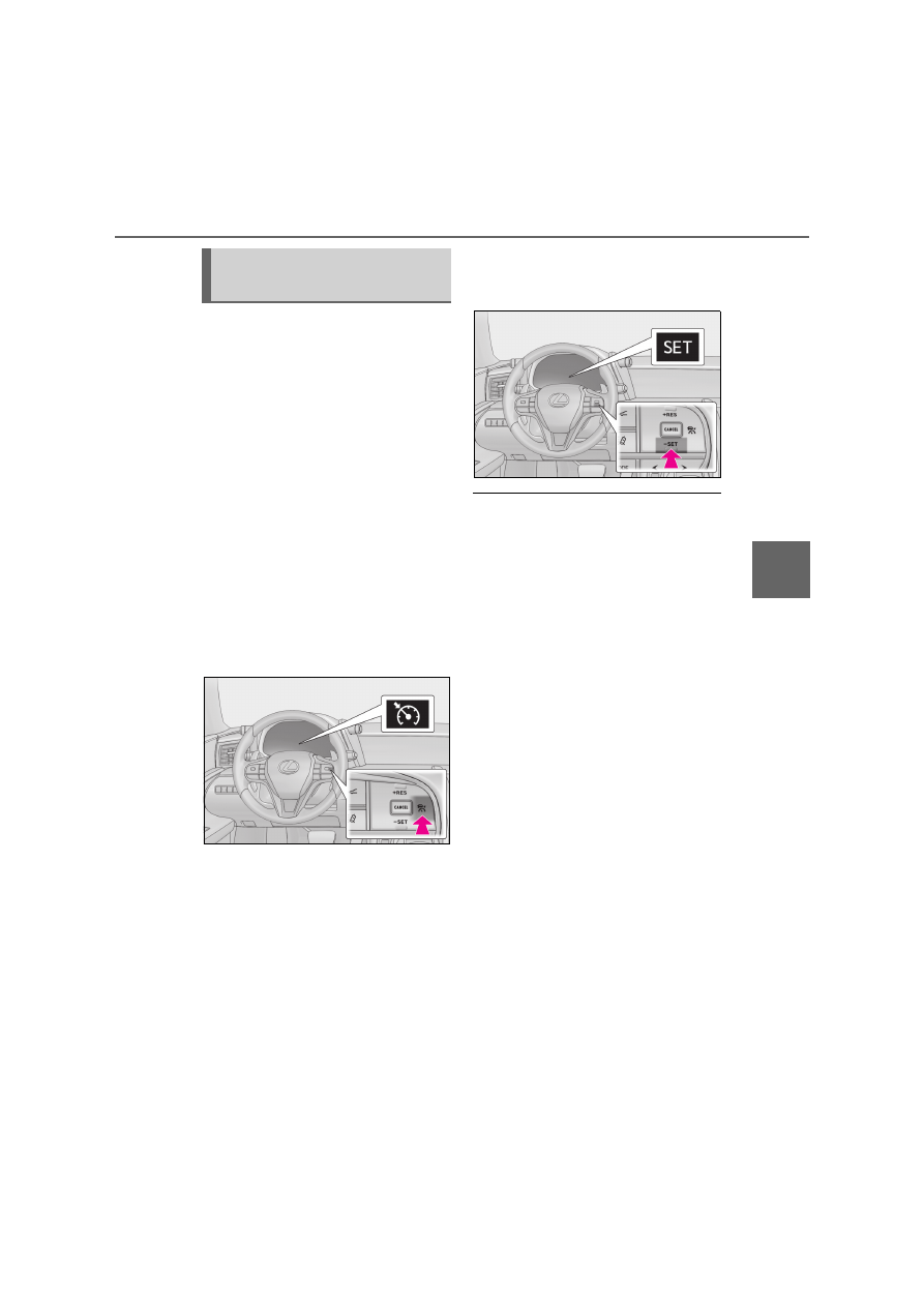
1

With the cruise control off, press 
and hold the cruise control main 
switch for 1.5 seconds or more.

Immediately after the switch is pressed, the 

radar cruise control indicator will come on. 

Afterwards, it switches to the cruise con-

trol indicator.
Switching to constant speed control mode 

is only possible when operating the switch 

with the cruise control off.

2

Accelerate or decelerate, with 
accelerator pedal operation, to the 
desired vehicle speed (at or above 
approximately 40 km/h [25 mph]) 
and press the “-SET” switch to set 
the speed.

Cruise control “SET” indicator will come 

on.
The vehicle speed at the moment the 

switch is released becomes the set speed.

Adjusting the speed setting: 

P.256

Canceling and resuming the speed setting: 

P.258

Q

Dynamic radar cruise control with full-

speed range can be set when

O

The shift position is in D.

O

Range 4 or higher of D has been selected 

by using the paddle shift switch.

O

Vehicle speed is at or above approxi-

mately 50 km/h (30 mph).

However, when a preceding vehicle is 

detected, the dynamic radar cruise con-

trol with full-speed range can be set even 

if the vehicle speed is below approxi-

mately 50 km/h (30 mph).

Q

Accelerating after setting the vehicle 

speed

The vehicle can accelerate by operating the 

accelerator pedal. After accelerating, the 

set speed resumes. However, during vehi-

cle-to-vehicle distance control mode, the 

vehicle speed may decrease below the set 

speed in order to maintain the distance to 

the preceding vehicle.

Q

When the vehicle stops while follow-up 

cruising

O

Pressing the “+RES” switch while the 

vehicle ahead stops will resume follow-

up cruising if the vehicle ahead starts off 

within approximately 3 seconds after the 

switch is pressed.

O

If the vehicle ahead starts off within 3 sec-

onds after your vehicle stops, follow-up 

cruising will be resumed.

Selecting constant speed con-
trol mode

260

4-5. Using the driving support systems

Q

Automatic cancelation of vehicle-to-

vehicle distance control mode

Vehicle-to-vehicle distance control mode is 

automatically canceled in the following situ-

ations:

O

Actual vehicle speed falls at or below 

approximately 40 km/h (25 mph) when 

there are no vehicles ahead.

O

The preceding vehicle leaves the lane 

when your vehicle is following at a vehicle 

speed at or below approximately 40 

km/h (25 mph). Otherwise, the sensor 

can not properly detect the vehicle. 

(“CRUISE NOT AVAILABLE No Pre-

ceding Vehicles” is displayed on the 

multi-information display)

O

VSC is activated.

O

TRC is activated for a period of time.

O

When the VSC or TRC system is turned 

off.

O

When snow mode is set.

O

The sensor cannot detect correctly 

because it is covered in some way.

O

Pre-collision braking is activated.

O

The parking brake is operated.

O

The vehicle is stopped by system control 

on a steep incline.

O

The following are detected when the 

vehicle has been stopped by system con-

trol:

• The driver is not wearing a seat belt.

• The driver’s door is opened.

• The vehicle has been stopped for about 3 

minutes

If vehicle-to-vehicle distance control mode 
is automatically canceled for any other rea-
son, there may be a malfunction in the sys-
tem. Contact any authorized Lexus retailer 
or Lexus authorized repairer, or any reli-
able repairer.

Q

Automatic cancelation of constant 

speed control mode

Constant speed control mode is automati-

cally canceled in the following situations:

O

Actual vehicle speed is more than 

approximately 16 km/h (10 mph) below 

the set vehicle speed.

O

Actual vehicle speed falls below approxi-

mately 40 km/h (25 mph).

O

VSC is activated.

O

TRC is activated for a period of time.

O

When the VSC or TRC system is turned 

off.

O

Pre-collision braking is activated.

If constant speed control mode is automati-
cally canceled for any other reason, there 
may be a malfunction in the system. Con-
tact any authorized Lexus retailer or Lexus 
authorized repairer, or any reliable 
repairer.

Q

Brake system operation sound

If the brakes are applied automatically while 

the vehicle is in vehicle-to-vehicle distance 

control mode, a brake system operation 

sound may be heard. This does not indicate 

a malfunction.

Q

If “Radar Cruise Control Unavailable” is 

shown on the multi-information display

The radar cruise control system cannot be 

used temporarily. Use the system when it 

becomes available again.

Q

Warning messages and buzzers for 

dynamic radar cruise control with full-

speed range

Warning messages and buzzers are used to 

indicate a system malfunction or to inform 

the driver of the need for caution while driv-

ing. If a warning message is shown on the 

multi-information display, read the message 

and follow the instructions.

Q

When the sensor may not be correctly 

detecting the vehicle ahead

In the case of the following and depending 

on the conditions, operate the brake pedal 

when deceleration of the system is insuffi-

cient or operate the accelerator pedal 

when acceleration is required.
As the sensor may not be able to correctly 

detect these types of vehicles, the approach 

warning (

P.258) may not be activated.

261

4

4-5. Using the driving support systems

Dr

ivin
g

O

Vehicles that cut in suddenly

O

Vehicles traveling at low speeds

O

Vehicles that are not moving in the same 

lane

O

Vehicles with small rear ends (trailers 

with no load on board, etc.)

O

Motorcycles traveling in the same lane

O

When water or snow thrown up by the 

surrounding vehicles hinders the detect-

ing of the sensor

O

When your vehicle is pointing upwards 

(caused by a heavy load in the luggage 

compartment, etc.)

O

Preceding vehicle has an extremely high 

ground clearance

Q

Conditions under which the vehicle-to-

vehicle distance control mode may not 

function correctly

In the case of the following conditions, 

operate the brake pedal (or accelerator 

pedal, depending on the situation) as nec-

essary.
As the sensor may not be able to correctly 

detect vehicles ahead, the system may not 

operate properly.

O

When the road curves or when the lanes 

are narrow

O

When steering wheel operation or your 

position in the lane is unstable

O

When the vehicle ahead of you deceler-

ates suddenly

O

When driving on a road surrounded by a 

structure, such as in a tunnel or on a 

bridge

O

While the vehicle speed is decreasing to 

the set speed after the vehicle acceler-

ates by depressing the accelerator pedal

262

4-5. Using the driving support systems

1

Normal mode/Custom mode

Normal mode and custom mode are 
selected by pressing the driving mode 
select switch. Each time the switch is 
pressed, the driving mode changes 
between normal mode and custom mode. 
When custom mode is selected, the “Cus-
tom” indicator comes on.
Press the switch to change the driving 
mode to normal mode when not in normal 
mode.
• Normal mode
Provides an optimal balance of fuel econ-
omy, quietness, and dynamic performance. 
Suitable for city driving.
When the shift position is in D, an appropri-

ate gear for sporty driving may automati-
cally be selected according to driver 
performance and driving conditions.
• Custom mode
Allows you to drive with the power train, 
chassis and air conditioning system func-
tions set to your preferred settings.
Custom mode settings can only be 
changed on the drive mode customization 
display of Center Display. (

P.301)

2

Comfort mode

By controlling the suspension, riding com-
fort is further enhanced. Suitable for city 
driving.
When not in comfort mode and the driving 
mode select switch is turned forward, the 
“Comfort” indicator comes on.

3

Eco drive mode

Helps the driver accelerate in an eco-
friendly manner and improve fuel economy 
through moderate throttle characteristics 
and by controlling the operation of the air 
conditioning system (heating/cooling).
When in comfort mode, if the driving mode 
select switch is turned forward, the “Eco” 
indicator comes on.

4

Sport mode

• SPORT  S  mode
Controls the transmission and engine to 
provide quick, powerful acceleration. This 
mode is suitable for when agile driving 
response is desired, such as when driving 
on roads with many curves.
When not in SPORT S mode, if the driving 
mode select switch is turned backward, the 
“Sport S” indicator comes on.
• SPORT  S+  mode
Provides earlier downshift timing than 
SPORT S mode in order to maintain a high 
engine speed and provides faster gear 
changes. This mode also changes the 

Driving mode select switch

The driving modes can be selected 
to suit driving condition.

Selecting the driving mode

263

4

4-5. Using the driving support systems

Dr

ivin
g

steering feel, suspension control and 
VDIM control, making it suitable for pow-
erful sporty driving.
When in SPORT S mode, if the driving 
mode select switch is turned backward, the 
“Sport S+” indicator comes on.

Q

Operation of the air conditioning sys-

tem in Eco drive mode

Eco drive mode controls the heating/cool-

ing operations and fan speed of the air con-

ditioning system to enhance fuel efficiency. 

To improve air conditioning performance, 

perform the following operations:

O

Adjust the fan speed (

P.307, 309)

O

Turn off Eco drive mode

Q

Automatic deactivation of sport mode 

and custom mode

If the engine switch is turned off after driv-

ing in sport mode or custom mode, the 

drive mode will be changed to normal 

mode.

Q

Driving mode pop-up display

When the driving mode is changed, the 

selected driving mode will be temporarily 

displayed on the side display. (

P.303)

For custom mode, select “Setting” on the 

display to customize the driving mode.

Q

Types of sensors

Front corner sensors

Front center sensors

Rear corner sensors

Rear center sensors

Q

Display

When the sensors detect an obstacle, a 
graphic is shown on the multi-informa-
tion display, head-up display and Cen-
ter Display depending on the position 
and distance to the obstacle.

Multi-information display and head-

Lexus parking assist-sensor

The distance from your vehicle to 
nearby obstacles when parallel 
parking or maneuvering into a 
garage is measured by the sensors 
and communicated via the multi-
information display, head-up dis-
play (if equipped), Center Display 
and a buzzer. Always check the sur-
rounding area when using this sys-
tem.

System components

A
B
C
D

264

4-5. Using the driving support systems

up display

Front corner sensor detection

Front center sensor detection

Rear corner sensor detection

Rear center sensor detection

Center Display

A graphic is shown when the Lexus park-
ing assist monitor is displayed (insert dis-
play)
A simplified image is displayed on the 
upper right corner of Center Display when 
an obstacle is detected.

1

Press 

 or 

 of the meter con-

trol switches, and select 

.

2

Press 

 or 

 of the meter con-

trol switches, and select “Parking 
Assist”, and press “OK”.

When the Lexus parking assist-sensor 
is turned on, the Lexus parking assist-
sensor indicator comes on to inform 
the driver that the system is opera-
tional.

Q

The Lexus parking assist-sensor can be 

operated when

O

Front center sensors:

• The engine switch is in ON.

• The shift position is in a position other 

than P or R.

• The vehicle speed is less than about 10 

km/h (6 mph).

O

Front corner sensors:

• The engine switch is in ON.

• The shift position is in a position other 

than P.

• The vehicle speed is less than about 10 

km/h (6 mph). 

(At any speed when the shift position is in 

R)

O

Rear corner and rear center sensors:

• The engine switch is in ON.

• The shift position is in R.

Q

Muting the buzzer sound

O

To mute the buzzer sound:

The buzzer can be temporarily muted by 

pressing “OK” of the meter control 

switches while an obstacle detection dis-

play is shown on the multi-information dis-

play.

O

To cancel the mute:

Mute will be automatically canceled in the 

following situations.

• When the shift position is changed 

(except shifting from D to N, or N to D)

• When the vehicle speed has reached or 

exceeded 10 km/h (6 mph) with the shift 

position in D

• When the Lexus parking assist-sensor is 

turned off once and turned on again

Turning Lexus parking assist-
sensor on/off

A
B
C
D

265

4

4-5. Using the driving support systems

Dr

ivin
g

• When the engine switch is turned off 

once and turned to ON again

Q

If “Clean Parking Assist Sensor” is dis-

played on the multi-information display

A sensor may be dirty or covered with snow 

or ice. In such cases, if it is removed from 

the sensor, the system should return to nor-

mal.
Also, due to the sensor being frozen at low 

temperatures, a malfunction display may 

appear or an obstacle may not be detected. 

If the sensor thaws out, the system should 

return to normal.

Q

If “Parking Assist Malfunction” or 

“Parking Assist Malfunction Visit Your 

Dealer” is displayed on the multi-infor-

mation display

There is a malfunction and the device may 

not be working properly.
Have the vehicle inspected by any autho-

rized Lexus retailer or Lexus authorized 

repairer, or any reliable repairer.

Q

Sensor detection information

O

The sensor’s detection areas are limited 

to the areas around the vehicle’s front 

and rear bumpers.

O

Certain vehicle conditions and the sur-

rounding environment may affect the 

ability of the sensor to correctly detect 

obstacles. Particular instances where this 

may occur are listed below.

• There is dirt, snow or ice on the sensor. 

(Wiping the sensors will resolve this 

problem.)

• The sensor is frozen. (Thawing the area 

will resolve this problem.)

In especially cold weather, if a sensor is 

frozen the screen may show an abnormal 

display, or obstacles may not be 

detected.

• The sensor is covered in any way.

• The vehicle is leaning considerably to 

one side.

• On an extremely bumpy road, on an 

incline, on gravel, or on grass.

• The vicinity of the vehicle is noisy due to 

vehicle horns, motorcycle engines, air 

brakes of large vehicles, or other loud 

noises producing ultrasonic waves.

• There is another vehicle equipped with 

parking assist sensor in the vicinity.

• The sensor is splashed with water or 

heavy rain.

• The vehicle is equipped with a fender 

pole or wireless antenna.

• Towing eyelets are installed.

• The bumper or sensor receives a strong 

impact.

• The vehicle is approaching a tall or 

curved curb.

• In harsh sunlight or intense cold weather.

• The area directly under the bumpers is 

not detected.

• If obstacles draw too close to the sensor.

• A non-genuine Lexus suspension (low-

ered suspension etc.) is installed.

• People may not be detected if they are 

wearing certain types of clothing.

In addition to the examples above, there are 
instances in which, because of their shape, 
signs and other objects may be judged by 
the sensor to be closer than they are.

O

The shape of the obstacle may prevent 

the sensor from detecting it. Pay particu-

lar attention to the following obstacles:

• Wires, fences, ropes, etc.

• Cotton, snow and other materials that 

absorb sound waves

• Sharply-angled objects

• Low  obstacles

• Tall obstacles with upper sections pro-

jecting outwards in the direction of your 

vehicle

O

The following situations may occur 

during use.

• Depending on the shape of the obstacle 

and other factors, the detection distance 

may shorten, or detection may be impos-

sible.

• Obstacles may not be detected if they 

are too close to the sensor.

• There will be a short delay between 

obstacle detection and display. Even at 

slow speeds, there is a possibility that the 

obstacle will come within the sensor’s 

detection areas before the display is 

shown and the warning beep sounds.

• Thin posts or objects lower than the sen-

sor may not be detected when 

approached, even if they have been 

266

4-5. Using the driving support systems

detected once.

• It might be difficult to hear beeps due to 

the volume of the audio system or air flow 

noise of the air conditioning system.

• It might be difficult to hear beeps due to 

the sounds of other systems.

Q

Customization

Some functions can be customized. 

(

P.435)

Q

Detection range of the sensors

Approximately 100 cm (3.3 ft.)

Approximately 150 cm (4.9 ft.)

Approximately 60 cm (2.0 ft.)

WARNING

Q

When using the Lexus parking assist-

sensor

Observe the following precautions.
Failing to do so may result in the vehicle 

being unable to be driven safely and pos-

sibly cause an accident.

O

Do not use the sensor at speeds in 

excess of 10 km/h (6 mph).

O

The sensors’ detection areas and reac-

tion times are limited. When moving 

forward or reversing, check the areas 

surrounding the vehicle (especially the 

sides of the vehicle) for safety, and 

drive slowly, using the brake to control 

the vehicle’s speed.

O

Do not install accessories within the 

sensors’ detection areas.

NOTICE

Q

When using Lexus parking assist-sen-

sor

In the following situations, the system 

may not function correctly due to a sen-

sor malfunction etc. Have the vehicle 

checked by any authorized Lexus 

retailer or Lexus authorized repairer, or 

any reliable repairer.

O

The Lexus parking assist-sensor oper-

ation display flashes or shows continu-

ously, and a beep sounds when no 

obstacles are detected.

O

If the area around a sensor collides 

with something, or is subjected to 

strong impact.

O

If the bumper or grille collides with 

something.

O

If the display flashes or shows continu-

ously without beeping, except when 

the mute function has been turned on.

O

If a display error occurs, first check the 

sensor. 

If the error occurs even when there is 

no ice, snow or mud on the sensor, it is 

likely that the sensor is malfunctioning.

Q

Notes when washing the vehicle

Do not apply intensive bursts of water or 

steam to the sensor area.
Doing so may result in the sensor mal-

functioning.

Sensor detection display, obsta-
cle distance

A
B
C

267

4

4-5. Using the driving support systems

Dr

ivin
g

The diagram shows the detection range of 
the sensors. Note that the sensors cannot 
detect obstacles that are extremely close 
to the vehicle.
The range of the sensors may change 
depending on the shape of the object etc.

Q

Multi-information display, head-up 
display and Center Display

Sensors that detect an obstacle will illu-
minate continuously or blink.

*1

: The illustrations show the graphics on 

the Multi-information display, and differ 
from the graphics on the head-up dis-
play and Center Display. Depending on 
the distance of the obstacle, the sensor 
display on Center Display illuminates or 
blinks in various cycles, although the 
width of it does not change.

*2

: Multi-information display and head-up 

display

*3

: Center  Display

Q

Buzzer operation and distance to 
an obstacle

A buzzer sounds when the sensors are 
operating.

The buzzer beeps faster as the vehi-
cle approaches an obstacle. When 

Display

*1

Approximate distance 

to obstacle

(continuous

*2

 or 

blinking 

slowly

*3

)

Front center sensor:
100 cm (3.3 ft.) to 50 
cm (1.6 ft.)
Rear center sensor:
150 cm (4.9 ft.) to 60 
cm (2.0 ft.)

(continuous

*2

or 

blinking

*3

)

Front center sensor:
50 cm (1.6 ft.) to 40 cm 
(1.3 ft.)
Rear center sensor:
60 cm (2.0 ft.) to 45 
cm (1.5 ft.)
Front and rear corner 
sensor:
60 cm (2.0 ft.) to 45 
cm (1.5 ft.)

(continuous

*2

 or 

blinking rap-

idly

*3

)

Front center sensor:
40 cm (1.3 ft.) to 30 cm 
(1.0 ft.)
Rear center sensor:
45 cm (1.5 ft.) to 35 cm 
(1.1 ft.)
Front and rear corner 
sensor:
45 cm (1.5 ft.) to 30 cm 
(1.0 ft.)

(blinking

*2

 or 

continuous

*3

)

Front center sensor:
Less than 30 cm (1.0 ft.)
Rear center sensor:
Less than 35 cm (1.1 ft.)
Front and rear corner 
sensor:
Less than 30 cm (1.0 ft.)

Display

*1

Approximate distance 

to obstacle

268

4-5. Using the driving support systems

the vehicle comes within the follow-
ing distance of the obstacle, the 
buzzer sounds continuously:

• Front center sensors: Approximately 30 

cm (1.0 ft.)

• Corner sensors: Approximately 30 cm 

(1.0 ft.)

• Rear center sensors: Approximately 35 

cm (1.1 ft.)

When 2 or more obstacles are 
detected simultaneously, the buzzer 
system responds to the nearest 
obstacle. If one or both come within 
the above distances, the beep will 
repeat a long tone, followed by fast 
beeps.

*

: If  equipped

BSM (Blind Spot Monitor)

*

The Blind Spot Monitor uses the 
sensors installed behind the rear 
bumper. The system is intended to 
assist the driver check areas that 
are not easily visible. The system 
has the following 2 functions:

The BSM (Blind Spot Monitor) 
function

Assists the driver in making a deci-
sion when changing lanes

The RCTA (Rear Crossing Traffic 
Alert) function

Assists the driver when backing up

These functions use same sensors.

System components

269

4

4-5. Using the driving support systems

Dr

ivin
g

Multi-information display

The BSM function/RCTA function can be 
turned on/off.
The RCTA function is available when the 
BSM function is on.

Outside rear view mirror indicators

BSM function: 
When a vehicle is detected in a blind spot 
of the outside rear view mirrors or 
approaching rapidly from behind into a 
blind spot, the outside rear view mirror 
indicator on the detected side will illumi-
nate. If the turn signal lever is operated 
toward the detected side, the outside rear 
view mirror indicator will flash.
RCTA function: 
When a vehicle approaching from the right 
or left at the rear of the vehicle is detected, 
both outside rear view mirror indicators 
will flash.

BSM indicator/RCTA indicator

When the BSM function/RCTA function is 
turned on, the indicator comes on.

Monitor screen display (RCTA 
function only)

If a vehicle approaching from the right or 
left at the rear of the vehicle is detected, 
the RCTA icon (

P.287) for the detected 

side will be displayed on the monitor 
screen. This illustration shows an example 
of a vehicle approaching from the left at 
the rear of the vehicle.

RCTA buzzer (RCTA function 
only)

If a vehicle approaching from the right or 
left at the rear of the vehicle is detected, a 
buzzer will sound. The buzzer also sounds 
for approximately 1 second immediately 
after the BSM function is operated to turn 
the system on.

1

Press 

 or 

 of the meter con-

trol switches, select 

.

2

Press 

 or 

 of the meter con-

trol switches, select “BSM”, and 
press “OK”.

3

Press 

 or 

 of the meter con-

trol switches, select “BSM” or 
“RCTA”, and press “OK”.

Q

Outside rear view mirror indicator visi-

bility

In strong sunlight, the outside rear view mir-

ror indicator may be difficult to see.

Q

Hearing the RCTA buzzer

The RCTA buzzer may be difficult to hear 

over loud noises, such as if the audio system 

volume is high.

Q

When “Blind Spot Monitor Unavailable” 

is shown on the multi-information dis-

play

Water, snow, mud, etc., may be built up in 

the vicinity of the sensor area of the 

bumper. (

P.282) Removing the water, 

snow, mud, etc., from the vicinity of the sen-

sor area of the bumper should return it to 

normal.
Also, the sensor may not function normally 

when used in extremely hot or cold 

weather.

Q

When “Blind Spot Monitor System Mal-

function Visit Your Dealer” is shown on 

the multi-information display

There may be a sensor malfunction or volt-

age abnormality. Have the vehicle 

inspected at any authorized Lexus retailer 

or Lexus authorized repairer, or any reli-

able repairer.

Q

Customization

Some functions can be customized.

A

B

C

D

E

Turning the BSM func-
tion/RCTA function on/off

283

4

4-5. Using the driving support systems

Dr

ivin
g

WARNING

O

Keep the sensors and the surrounding 

areas on the rear bumper clean at all 

times.

If a sensor or its surrounding area on 

the rear bumper is dirty or covered 

with snow, the Blind Spot Monitor may 

not operate and a warning message 

(

P.269) will be displayed. In this sit-

uation, clear off the dirt or snow and 

drive the vehicle with the operation 

conditions of the BSM function 

(

P.285) satisfied for approximately 

10 minutes. If the warning message 

does not disappear, have the vehicle 

inspected by any authorized Lexus 

retailer or Lexus authorized repairer, 

or any reliable repairer.

O

Do not subject a sensor or its sur-

rounding area on the rear bumper to a 

strong impact.

If a sensor is moved even slightly off 

position, the system may malfunction 

and vehicles may not be detected cor-

rectly.

In the following situations, have your 

vehicle inspected by any authorized 

Lexus retailer or Lexus authorized 

repairer, or any reliable repairer.

• A sensor or its surrounding area is 

subject to a strong impact.

• If the surrounding area of a sensor is 

scratched or dented, or part of them 

has become disconnected.

O

Do not disassemble the sensor.

O

Do not attach stickers to the sensor or 

surrounding area on the rear bumper.

O

Do not modify the sensor or surround-

ing area on the rear bumper.

O

Do not paint the rear bumper any 

color other than an official Lexus color.

284

4-5. Using the driving support systems

Q

Operation of the BSM function

The BSM function uses radar sensors to detect the following vehicles traveling in 
adjacent lanes and advises the driver of the presence of such vehicles via the indi-
cators on the outside rear view mirrors.

Vehicles that are traveling in areas that are not visible using the outside rear 
view mirrors (the blind spots)

Vehicles that are approaching rapidly from behind in areas that are not visible 
using the outside rear view mirrors (the blind spots)

Q

BSM function detection areas

The areas that vehicles can be detected in are outlined below.

The range of each detection area is:

Approximately 0.5 m (1.6 ft.) to 3.5 m (11.5 ft.) from either side of the vehicle

*1

Approximately 1 m (3.3 ft.) forward of the rear bumper

Approximately 3 m (9.8 ft.) from the rear bumper

Approximately 3 m (9.8 ft.) to 60 m (197 ft.) from the rear bumper

*2

*1

: The area between the side of the vehicle and 0.5 m (1.6 ft.) from the side of the vehicle 

BSM function

A

B

A
B
C
D

285

4

4-5. Using the driving support systems

Dr

ivin
g

cannot be detected.

*2

: The greater the difference in speed between your vehicle and the detected vehicle is, 

the farther away the vehicle will be detected, causing the outside rear view mirror indi-
cator to illuminate or flash.

Q

The BSM function is operational when

The BSM function is operational when all of 

the following conditions are met:

O

The BSM function is on.

O

The shift position is in a position other 

than R.

O

The vehicle speed is greater than 

approximately 16 km/h (10 mph).

Q

The BSM function will detect a vehicle 

when

The BSM function will detect a vehicle pres-

ent in the detection area in the following sit-

uations:

O

A vehicle in an adjacent lane overtakes 

your vehicle.

O

You overtake a vehicle in adjacent lane 

slowly.

O

Another vehicle enters the detection 

area when it changes lanes.

Q

Conditions under which the BSM func-

tion will not detect a vehicle

The BSM function is not designed to detect 

the following types of vehicles and/or 

objects:

O

Small motorcycles, bicycles, pedestrians, 
etc.

*

O

Vehicles traveling in the opposite direc-

tion

O

Guardrails, walls, signs, parked vehicles 
and similar stationary objects

*

O

Following vehicles that are in the same 
lane

*

O

Vehicles traveling 2 lanes away from 
your vehicle

*

O

Vehicles which are being overtaken rap-
idly by your vehicle.

*

*

: Depending on the conditions, detection 

of a vehicle and/or object may occur.

Q

Conditions under which the BSM func-

tion may not function correctly

O

The BSM function may not detect vehi-

cles correctly in the following situations:

• When the sensor is misaligned due to a 

strong impact to the sensor or its sur-

rounding area

• When mud, snow, ice, a sticker, etc. is 

covering the sensor or surrounding area 

on the rear bumper

• When driving on a road surface that is 

wet with standing water during bad 

weather, such as heavy rain, snow, or fog

• When multiple vehicles are approaching 

with only a small gap between each vehi-

cle

• When the distance between your vehicle 

and a following vehicle is short

• When there is a significant difference in 

speed between your vehicle and the 

vehicle that enters the detection area

• When the difference in speed between 

your vehicle and another vehicle is 

changing

• When a vehicle enters a detection area 

traveling at about the same speed as your 

vehicle

• As your vehicle starts from a stop, a vehi-

cle remains in the detection area

• When driving up and down consecutive 

steep inclines, such as hills, dips in the 

road, etc.

• When driving on roads with sharp bends, 

consecutive curves, or uneven surfaces

• When vehicle lanes are wide, or when 

driving on the edge of a lane, and the 

vehicle in an adjacent lane is far away 

from your vehicle

• When an accessory (such as a bicycle 

carrier) or towing eyelet is installed to the 

rear of the vehicle

• When there is a significant difference in 

height between your vehicle and the 

vehicle that enters the detection area

• Immediately after the BSM function is 

286

4-5. Using the driving support systems

turned on

O

Instances of the BSM function unneces-

sarily detecting a vehicle and/or object 

may increase in the following situations:

• When the sensor is misaligned due to a 

strong impact to the sensor or its sur-

rounding area

• When the distance between your vehicle 

and a guardrail, wall, etc. that enters the 

detection area is short

• When driving up and down consecutive 

steep inclines, such as hills, dips in the 

road, etc.

• When vehicle lanes are narrow, or when 

driving on the edge of a lane, and a vehi-

cle traveling in a lane other than the adja-

cent lanes enters the detection area

• When driving on roads with sharp bends, 

consecutive curves, or uneven surfaces

• When the tires are slipping or spinning

• When the distance between your vehicle 

and a following vehicle is short

• When an accessory (such as a bicycle 

carrier) or towing eyelet is installed to the 

rear of the vehicle

Q

Operation of the RCTA function

The RCTA function uses radar sensors to detect vehicles approaching from the 
right or left at the rear of the vehicle and alerts the driver of the presence of such 
vehicles by flashing the outside rear view mirror indicators and sounding a buzzer.

Approaching vehicles

Detection areas of approaching vehicles

WARNING

Q

Cautions regarding the use of the 

function

The driver is solely responsible for safe 

driving. Always drive safely, taking care 

to observe your surroundings.
The BSM function is a supplementary 

function which alerts the driver that a 

vehicle is in a blind spot of the outside 

rear view mirrors or is approaching rap-

idly from behind into a blind spot. Do not 

overly rely on the BSM function. As the 

function cannot judge if it is safe to 

change lanes, over reliance could lead to 

an accident resulting in death or serious 

injury.
As the system may not function correctly 

under certain conditions, the driver’s 

own visual confirmation of safety is nec-

essary.

RCTA function

A
B

287

4

4-5. Using the driving support systems

Dr

ivin
g

Q

RCTA icon display

When a vehicle approaching from the 
right or left at the rear of the vehicle is 
detected, the following will be dis-
played on the monitor screen

Q

RCTA function detection areas

The areas that vehicles can be detected in are outlined below.

The buzzer can alert the driver of faster 
vehicles approaching from farther away.

Display

Content

A vehicle is 
approaching from 
the left at the rear of 
the vehicle

A vehicle is 
approaching from 
the right at the rear 
of the vehicle

Vehicles are 
approaching from 
both sides of the 
vehicle

The RCTA function 
is malfunctioning 
(

P.269)

Display

Content


Content      ..     10      11      12      13     ..