Lexus SC300 / Lexus SC400. Manual - part 796


  Index      Lexus     Lexus SC300 / Lexus SC400 - service repair manual


Search            


Content   ..  794  795  796  797   ..


Lexus SC300 / Lexus SC400. Manual - part 796


DIAGNOSTIC CHART

(See page 

RS–48

).

(See page 

RS–49

).

SUPPLEMENTAL RESTRAINT SYSTEM

TROUBLESHOOTING

RS–79
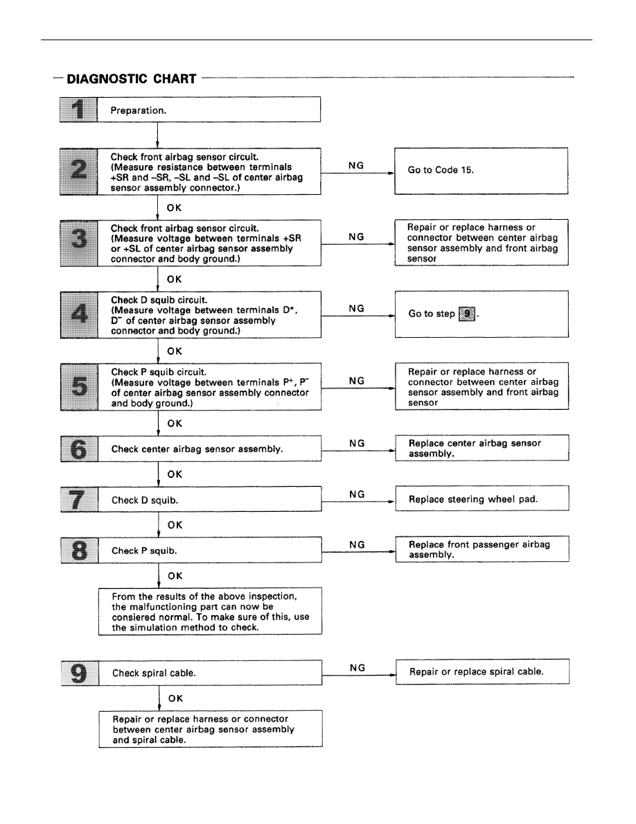
OK

NG

INSPECTION PROCEDURE

1

Preparation.

P

1.

Disconnect battery negative (–) terminal cable, and
wait at least 90 seconds.

2.

Remove steering wheel pad (See page 

RS–19

).

3.

Disconnect connectors of front passenger airbag
assembly (See page 

RS–32

).

Caution:

Store the steering wheel pad with the

front surface facing upward.

2

Check front airbag sensor circuit. (Measure resistance between terminals +SR and –SR, +SL
and –SL of center airbag sensor assembly connector.)

C

OK

P

Disconnect center airbag sensor assembly connector.

Measure resistance between terminals +SR and –Sr,
+SL and –SL of harness side connector of center airbag
sensor assembly.

Resistance:

755 


 – 855 


Go to code 15.

RS–80

SUPPLEMENTAL RESTRAINT SYSTEM

TROUBLESHOOTING

OK

NG

OK

NG

3

Check front airbag sensor circuit. (Measure voltage between terminals +SR or +SL of center
airbag sensor assembly connector and body ground.)

C

OK

P

1.

Connect negative (–) terminal cable to battery.

2.

Turn ignition switch ON.

Measure voltage between terminals +SR or +SL of har-
ness side connector of center airbag sensor assembly
and body ground.

Voltage:

Below 1 V

Repair or replace harness or connector between center
airbag sensor assembly and front airbag sensor (See
page 

RS–48

).

4

Check D squib circuit.

C

OK

P

Disconnect center airbag sensor assembly connector.

Measure resistance voltage between D+ and D– on spi-
ral cable side of connector between spiral cable and
steering wheel pad.

Voltage:

Below 1 V

Go to step 


SUPPLEMENTAL RESTRAINT SYSTEM

TROUBLESHOOTING

RS–81

OK

NG

OK

NG

5

Check P squib circuit.

C

OK

Measure voltage at P+ on spiral cable side of connector
between spiral cable and steering wheel pad.

Voltage:

Below 1 V

Go to step 


6

Check center airbag sensor assembly.

C

OK

Hint

P

1.

Turn ignition switch LOCK.

2.

Disconnect negative (–) terminal cable from bat-
tery.

3.

Connect connector to center airbag sensor assem-
bly.

4.

Using a service wire, connect D

+

 and D

 on spiral

cable side connector between spiral cable and
steering wheel pad.

5.

Using a service wire, connect P

+

 and P

 on center

airbag sensor assembly side of connector between
center airbag sensor assembly a dn front passen-
ger airbag assembly.

6.

Connect negative (–) terminal cable to battery, and
wait at least 2 seconds.

1.

Turn ignition switch ACC or ON and wait at least 20
seconds. 
Clear malfunction code. Turn ignition switch LOCK
and wait at least 20 seconds.

2.

Turn ignition switch ACC or ON, an s wait at least
20 seconds.

3.

Using SST, connect terminals Tc and E

1

 of DLC2

SST 09843–18020

4.

Check diagnostic trouble code.

Diagnostic trouble code 12 is not output.

Code other than code 12 may be output at this time, but
this is not relevant to this check.

Replace center airbag sensor assembly.

RS–82

SUPPLEMENTAL RESTRAINT SYSTEM

TROUBLESHOOTING


Content   ..  794  795  796  797   ..