Lexus SC300 / Lexus SC400. Manual - part 574
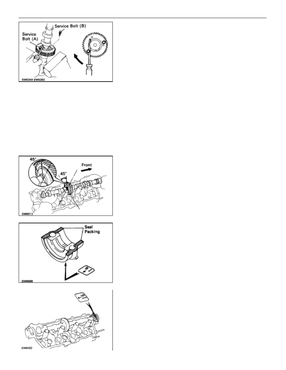
(d) Insert a service bolt (A) into the service hole of the
camshaft sub–gear.
(e) Using a screwdriver, align the service holes and teeth of
the camshaft driven gear and sub–gear by turning
camshaft sub–gear clockwise, and install a service bolt
(B).
NOTICE: Be careful not to damage the camshaft.
(f) Remove the service bolt (A).
7. INSTALL
CAMSHAFTS
NOTICE: Since the thrust clearance of the camshaft is
small, the camshaft must be held level while it is being
installed. If the camshaft is not kept level, the portion of
the cylinder head receiving the shaft thrust may crack or
be damaged causing the camshaft to seize or break. To
avoid this, the following steps should be carried out.
A.
Install intake camshaft to RH cylinder head
(a) Apply MP grease to the thrust portion of the camshaft.
(b) Place the intake camshaft at 45
°
angle of the timing
mark (one dot mark) on the cylinder head.
(c) Remove any old packing (FIPG) material.
(d) Apply seal packing to the bearing cap (mark ”I6”) as
shown.
Seal packing: Part No. 08826–00080 or equivalent
(e) Install the front bearing cap (mark ”I6”) with the arrow
mark facing rearward.
HINT:
•
Installing the front bearing cap will determine the thrust
position of the camshaft.
•
Align the arrow marks at front and rear of the cylinder
head with the mark on the bearing cap.
–
ENGINE MECHANICAL
Cylinder Heads
EM–95