Lexus SC300 / Lexus SC400. Manual - part 546
 

  Index      Lexus     Lexus SC300 / Lexus SC400 - service repair manual


Search            


Content   ..  544  545  546  547   ..


Lexus SC300 / Lexus SC400. Manual - part 546


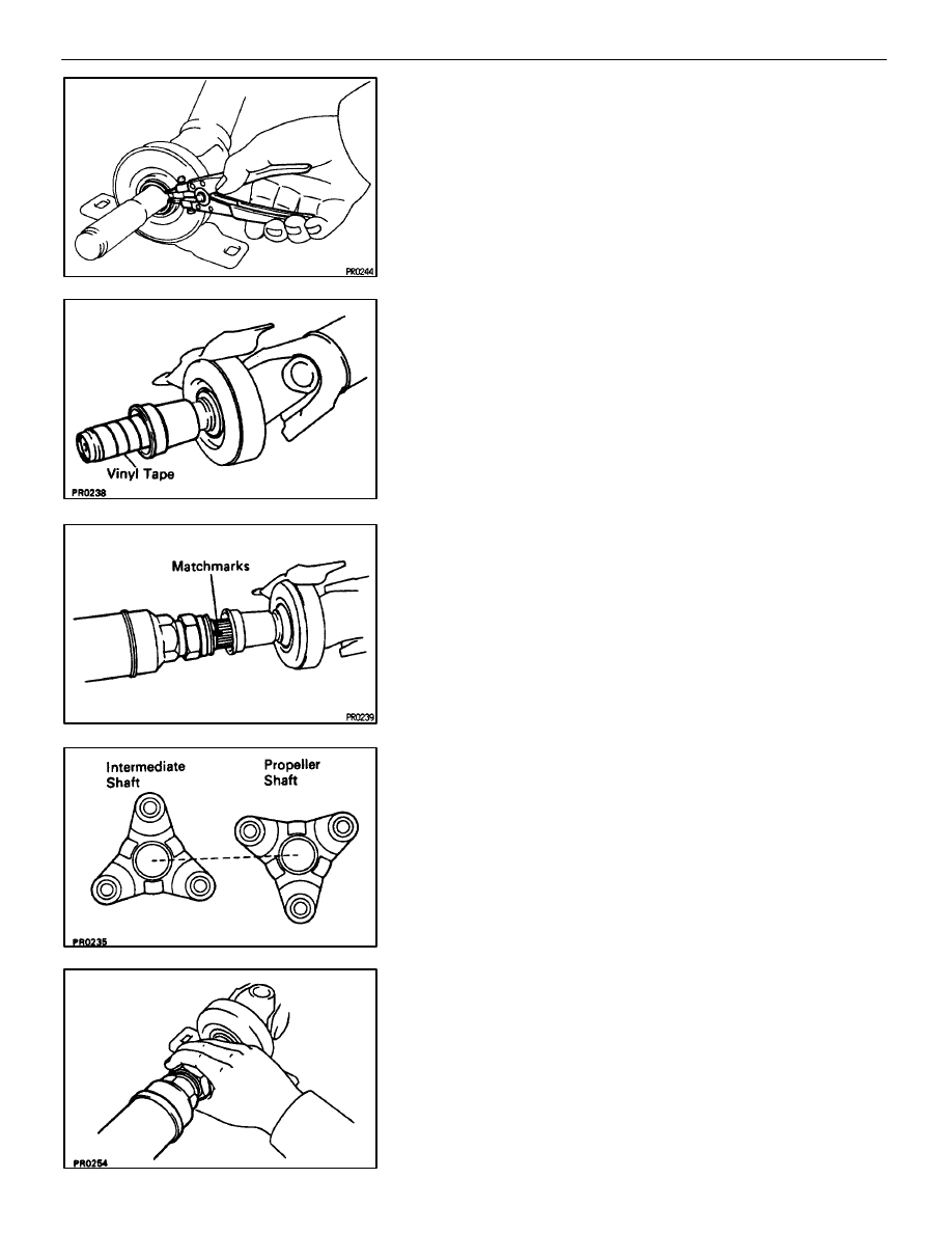
(d)  Using a snap ring expander, install the new snap ring.

6.  ASSEMBLE INTERMEDIATE SHAFT AND PROPELLER

SHAFT

(a)  Install the dust boot.

NOTICE: Assemble after wrapping vinyl tape around the
spline so it will not damage the boot.

(b)  Apply grease to the spline.

Grease:

Molybdenum disulphide lithium base, NLGI No.2.

(c)  Align the matchmarks and assemble the intermediate shaft

and propeller shaft.

(d)  Cover the adjusting nut with the dust boot.

NOTICE: The directions of the intermediate shaft com-
panion flange and the propeller shaft companion flange
should differ by 180

°

.

(e)  Tighten the adjusting nut fully by hand.

PROPELLER SHAFT

PROPELLER SHAFT

PR–11

PROPELLER SHAFT INSTALLATION

PR04L–01

1. 

INSTALL PROPELLER SHAFT

(a)  Apply grease to the flexible coupling centering bushings.

Grease:

Molybdenum disulphide lithium base, NLGI No.1 or

No.2.

(b)  Insert the propeller shaft from the vehicle’s rear and connect

the transmission and differential.
NOTICE: Support the center support bearing by hand so
that the transmission and intermediate shaft, and propel-
ler shaft and differential, remain in a straight line.

(c)  Temporarily install the center support bearing set bolts with

the adjusting washers.
HINT: Use the adjusting washers which were removed.

(d)  Align the matchmarks and connect the propeller shaft to the

transmission.

(e)  Install the 3 bolts, washers and nuts.

NOTICE: Bolts should be inserted from the propeller
shaft side.

Torque: 79 N

m (805 kgf

cm, 58 ft

lbf)

(g)  Align the matchmarks and install the propeller shaft on the

differential with the 3 bolts, washers and nuts.
NOTICE: Bolts should be inserted from the propeller
shaft side.

Torque: 79 N

m (805 kgf

cm, 58 ft

lbf)

PR–12

PROPELLER SHAFT

PROPELLER SHAFT

If using a new propeller shaft w / Phasemarks:
Install the propeller shaft phasemarks and differential phase-
marks so that their respective alignment phasemarks match.
If the propeller shaft phasemarks and differential phase-
marks do not align, install the propeller shaft and differential
alignment phasemarks are as close together as possible.
w / o Phasemarks:
Install the propeller shaft.
(See page 

PR–12

)

(h)  Torque the center support bearing set bolts.

Torque: 49 N

m (500 kgf

cm, 36 ft

lbf)

HINT: Adjust the center support bearing to keep the dimen-
sion within the limits, as shown.
Under the same condition, check if the center line of the cen-
ter support bearing is at right angles to the shaft axial direc-
tion.

(i) 

Using SST, tighten the adjusting nut.
SST 09922–10010

Torque: 48 N

m (490 kgf

cm, 35 ft

lbf)

HINT: Use a torque wrench with a fulcrum length of 350 mm
(13.8 in.).

2. 

INSPECT JOINT ANGLE
(See page

 PR–15

)

NOTICE: The joint angle should by all means be checked
when the propeller shaft is removed and installed.

3. 

INSTALL CROSSMEMBER BRACE
Install the center floor crossmember brace and torque the 4
bolts.

Torque: 13 N

m (130 kgf

cm, 8 ft

lbf)

PROPELLER SHAFT

PROPELLER SHAFT

PR–13

4. INSTALL 

HEAT 

INSULATOR

Install the heat insulator and torque the 4 nuts.

Torque: 5.4 N

m (55 kgf

cm, 48 in.

lbf)

5. 

INSTALL EXHAUST CENTER PIPE

(a)  Install new gaskets.
(b)  Install the exhaust center pipe.
(c)  Install the exhaust center pipe to the 2 rings.
(d)  Install and torque the new 4 nuts.

Torque: 19 N

m (195 kgf

cm, 14 ft

lbf)

6. 

INSTALL EXHAUST FRONT PIPE

(a)  Install new gaskets.
(b)  Install the front pipe.
(c)  Install and torque the 6 bolts and new nuts.

Torque: 43 N

m (440 kgf

cm, 32 ft

lbf)

(d)  Connect both oxygen sensors.

HINT: When connecting the oxygen sensor, turn it to the left
about 3 times.
NOTICE: After installing the oxygen sensor, check that
the wire is not twisted.

(e)  Tighten the oxygen sensors.

Torque: 44 N

m (450 kgf

cm, 33 ft

lbf)

(f)  Connect the oxygen sensor grommets to the floor.

PR–14

PROPELLER SHAFT

PROPELLER SHAFT


Content   ..  544  545  546  547   ..