Lexus SC300 / Lexus SC400. Manual - part 388
 

  Index      Lexus     Lexus SC300 / Lexus SC400 - service repair manual


Search            


Content   ..  386  387  388  389   ..


Lexus SC300 / Lexus SC400. Manual - part 388


CRANKSHAFT OIL SEALS
REPLACEMENT

EG0C0–0M

HINT: There are 2 methods (A and B) to replace the oil seal
which are as follows:

1. 

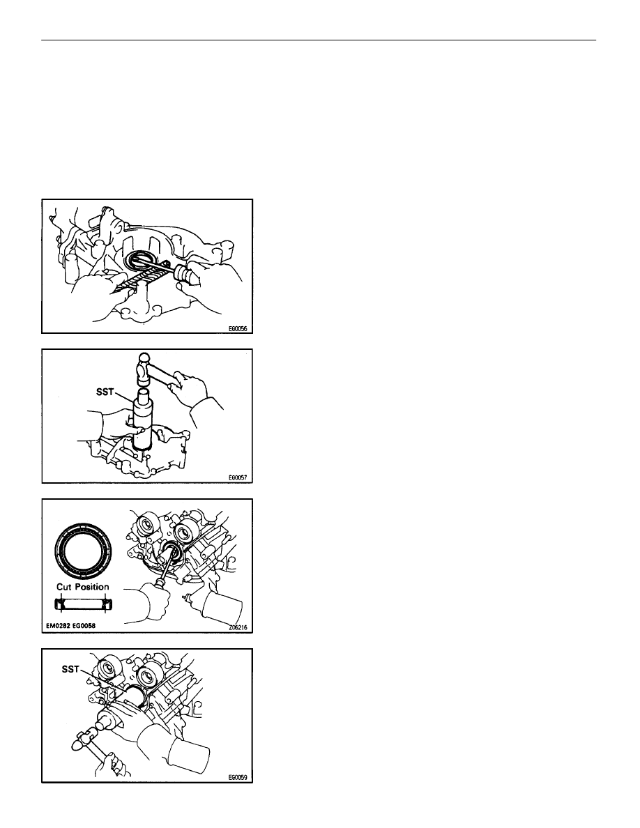
REPLACE CRANKSHAFT FRONT OIL SEAL

A.

If oil pump is removed from cylinder block:

(a)  Using a screwdriver, pry out the oil seal.

(b) Using 

SST and a hammer, tap in a new oil seal until its surface

is flush with the oil pump body edge.
SST 09316–60010 (09316–00010)

(c)  Apply MP grease to the oil seal lip.

B.

If oil pump is installed to the cylinder block:

(a)  Using a knife, cut off the oil seal lip.
(b)  Using a screwdriver, pry out the oil seal.

NOTICE: Be careful not to damage the crankshaft. Tape
the screwdriver tip.

(c)  Apply MP grease to a new oil seal lip.
(d)  Using SST and a hammer, tap in the oil seal until its surface

is flush with the oil pump body edge.
SST 09316–60010 (09316–00010)

1UZ–FE ENGINE

ENGINE MECHANICAL

EG–175

2. 

REPLACE CRANKSHAFT REAR OIL SEAL

A.

If rear oil seal retainer is removed from cylinder block:

(a)  Using a screwdriver and hammer, tap out the oil seal.

(b) Using 

SST and a hammer, tap in a new oil seal until its surface

is flush with the rear oil seal retainer edge.
SST 09223–56010

(c)  Apply MP grease to the oil seal lip.

B.

If rear oil seal retainer is installed to cylinder block:

(a)  Using a knife, cut off the oil seal lip.
(b)  Using a screwdriver, pry out the oil seal.

NOTICE: Be careful not to damage the crankshaft. Tape
the screwdriver tip.

(c)  Apply MP grease to a new oil seal lip.
(d)  Using SST and a hammer, tap in the oil seal until its surface

is flush with the rear oil seal retainer edge.
SST 09223–56010

EG–176

1UZ–FE ENGINE

ENGINE MECHANICAL

PISTON AND CONNECTING ROD
ASSEMBLY

EG0C1–07

1. 

ASSEMBLE PISTON AND CONNECTING ROD

(a) Using 

small screwdriver, install a new snap ring on one side

of the piston pin hole.

(b)  Gradually heat the piston to about 60


C (140


F).

(c)  Coat the piston pin with engine oil.
(d) Position 

the piston front mark with respect to the outside mark

on the connecting rod as shown in the diagram.
NOTICE: The installation direction of the piston and con-
necting rod are different for the RH and LH banks. The RH
piston is marked with “R”, the LH piston with “L”.

(e)  Align the piston pin holes of the piston and connecting rod,

and push in the piston pin with your thumb.

(f) Using 

small screwdriver, install a new snap ring on the other

side of the piston pin hole.

1UZ–FE ENGINE

ENGINE MECHANICAL

EG–177

2. INSTALL 

PISTON 

RINGS

(a)  Install the oil ring expander and 2 side rails by hand.

(b)  Using a piston ring expander, install the 2 compression rings

with the code mark facing upward.

Code mark:

No.1

1R or T

No.2

2R or 2T

(c)  Position the piston rings so that the ring ends are as shown.

NOTICE: Do not align the ring ends.

3. INSTALL 

BEARINGS

(a)  Align the bearing claw with the groove of the connecting rod

or connecting cap.

(b)  Install the bearings in the connecting rod and connecting rod

cap.

EG–178

1UZ–FE ENGINE

ENGINE MECHANICAL


Content   ..  386  387  388  389   ..