Lexus SC300 / Lexus SC400. Manual - part 330
 

  Index      Lexus     Lexus SC300 / Lexus SC400 - service repair manual


Search            


Content   ..  328  329  330  331   ..


Lexus SC300 / Lexus SC400. Manual - part 330


7. 

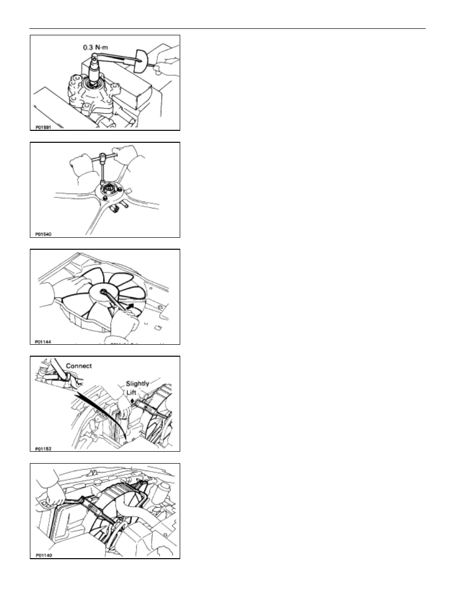
INSTALL DRIVE SHAFT PRELOAD
(a)  Check that the drive shaft rotates smoothly without

abnormal noise.

(b)  Temporarily install the pulley nut, and check the rotating

torque.

Rotating torque:

0.3 N

m (3.0 kgf

cm, 2.6 in.

lbf)

INSTALLATION OF HYDRAULIC MOTOR

(See Components on page 

CO–47

)

1. 

INSTALL HYDRAULIC MOTOR TO FAN SHROULD
Install the hydraulic motor with the three bolts.

Torque: 4.9 N

m (50 kgf

cm, 43 in.

lbf)

2. 

INSTALL COOLING FAN TO HYDRAULIC MOTOR
Install the fan with the plate washer bolt.
Tighten the nut by turning it counterclockwise.

Torque: 15 N

m (150 kgf

cm, 11 ft

lbf)

3. INSTALL 

RADIATOR 

FAN 

SHROULD

(a)  Place the fan shrould on the radiator.
(b) Slightly 

lift the fan shrould, and connect the two oil cooler

hoses (for cooling fan) to the hose clamp on the fan
shrould.

(c)  Install the fan shrould with the four bolts.

Torque: 4.9 N

m (50 kgf

cm, 43 in.

lbf)

COOLIING SYSTEM

Electronically Controlled Hydraulic Cooling Fan
(Hydraulic Motor)

CO–55

(d)  Install the wire clamp to the fan shrould.

4.  INSTALL COOLING FAN RESERVOIR TANK TO FAN

SHROULD
(a)  Install the reservoir tank with the four bolts.

Torque: 4.9 N

m (50 kgf

cm, 43 in.

lbf)

(b)  Install the suction hose to the clamp on the fan shrould.

5. 

INSTALL COOLING FAN INLET PIPE TO FAN SHROULD
Install the inlet pipe with the two bushings, brackets and
bolts.

Torque: 4.9 N

m (50 kgf

cm, 43 in.

lbf)

6. CONNECT 

HOSES

Connect the following hoses:

(1) Pressure 

hose 

to 

hydraulic 

motor 

Connect the

pressure hose with a new gasket and union bolt.

Torque: 64 N

m (650 kgf

cm, 47 ft

lbf)

(2)  Return hose to hydraulic motor.

(3)  Upper radiator hose to radiator.

CO–56

COOLIING SYSTEM

Electronically Controlled Hydraulic Cooling Fan
(Hydraulic Motor)

7. INSTALL 

RADIATOR 

RESERVOIR 

TANK

(a)  Install the reservoir tank to the reservoir tank bracket.
(b)  Install the reservoir tank bracket with two bolts.

Torque: 4.9 N

m (50 kgf

cm, 43 in.

lbf)

(c)  Connect the following hoses:

(1)  Reservoir hose to water inlet housing
(2)  Reservoir hose to radiator

(d)  Connect the coolant level sensor connector.

8. INSTALL 

BATTERY

9. 

FILL ENGINE WITH COOLANT (See page 

CO–7

)

10.  FILL COOLING FAN RESERVOIR TANK WITH FLUID

(See pages 

CO–23

 and 24)

11.  START ENGINE AND CHECK FOR LEAKS
12.  INSTALL ENGINE UNDER COVER

COOLIING SYSTEM

Electronically Controlled Hydraulic Cooling Fan
(Hydraulic Motor)

CO–57

Oil Cooler

COMPONENTS FOR REMOVAL AND
INSTALLATION

REMOVAL OF OIL COOLER

1. 

REMOVE FENDER LINER

2. 

DISCONNECT PS OIL COOLER
Remove the two bolts, and disconnect the PS oil cooler from
cooling fan oil cooler.

3. 

DISCONNECT HOSES FROM OIL COOLER
Disconnect the following hoses:

(1)  Inlet hose (from reservoir tank)
(2)  Outlet hose (from hydraulic motor)

CO–58

COOLIING SYSTEM

Electronically Controlled Hydraulic 
Cooling Fan (Oil Cooler)


Content   ..  328  329  330  331   ..