Lexus SC300 / Lexus SC400. Manual - part 329
 

  Index      Lexus     Lexus SC300 / Lexus SC400 - service repair manual


Search            


Content   ..  327  328  329  330   ..


Lexus SC300 / Lexus SC400. Manual - part 329


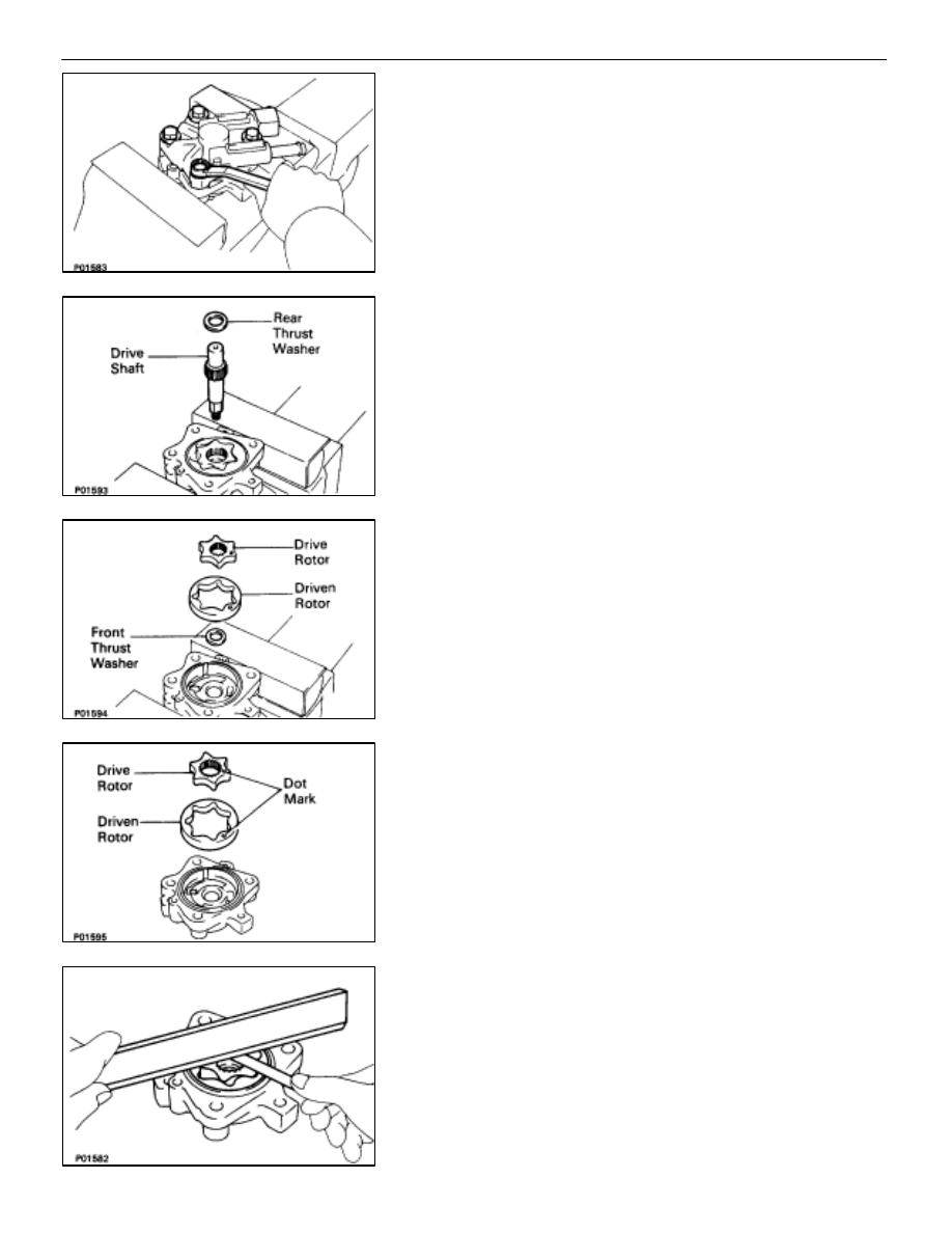
DISASSEMBLY OF HYDRAULIC MOTOR

(See Components on page 

CO–50

)

1. MOUNT 

MOTOR 

HOUSING

Slightly mount the motor housing in a vise.
NOTICE: Be careful not to damage the motor housing.

2. REMOVE 

MOTOR 

COVER

(a)  Remove the four bolts and motor cover.
(b)  Remove the O–ring from the motor housing.

3. 

REMOVE REAR THRUST WASHER AND DRIVE SHAFT

4. 

REMOVE DRIVE AND DRIVEN ROTORS

5. 

REMOVE FRONT THRUST WASHER

INSPECTION OF HYDRAULIC MOTOR

1. 

INSPECT DRIVE AND DRIVEN ROTORS
(a)  Install the drive and driven rotor to the motor housing

with the dot mark facing upward.

(b)  Using a feeler gauge and precision straight edge,

measure the side clearance between the rotor and
precision straight edge.

Standard side clearance: 0.01–0.04 mm

(0.0004–0.0016 in.)

Maximum side clearance: 0.05 mm (0.0020 in.)

If the clearance is greater than maximum, replace the rotors
as a set. If necessary, replace the motor assembly.

COOLIING SYSTEM

Electronically Controlled Hydraulic Cooling Fan
(Hydraulic Motor)

CO–51

HINT: When replacing the rotors, select the rotor set accord-
ing to the imprinted mark on the motor housing.

ÑÑÑÑÑÑÑÑÑÑ

ÑÑÑÑÑÑÑÑÑÑ

Imprinted mark on housing

ÑÑÑÑÑÑÑÑÑÑÑÑÑ

ÑÑÑÑÑÑÑÑÑÑÑÑÑ

Rotor set

ÑÑÑÑÑÑÑÑÑÑ

1

ÑÑÑÑÑÑÑÑÑÑÑÑÑ

16906–50010

ÑÑÑÑÑÑÑÑÑÑ

ÑÑÑÑÑÑÑÑÑÑ

2

ÑÑÑÑÑÑÑÑÑÑÑÑÑ

ÑÑÑÑÑÑÑÑÑÑÑÑÑ

16906–50020

ÑÑÑÑÑÑÑÑÑÑ

ÑÑÑÑÑÑÑÑÑÑ

3

ÑÑÑÑÑÑÑÑÑÑÑÑÑ

ÑÑÑÑÑÑÑÑÑÑÑÑÑ

16906–50030

2. 

INSPECT OIL CLEARANCE OF DRIVE SHAFT
(a)  Using a caliper gauge, measure the shaft hole inside

diameter of the housing and cover.

Shaft hole inside diameter: 14.000–14.011 mm

(0.5512–0.5516 in.)

(b)  Using a micrometer, measure the drive shaft diameter.

Shaft diameter: 13.973–13.984 mm

(0.5501–0.5506 in.)

(c) Subtract 

the drive shaft diameter measurement from the

shaft hole diameter measurement.

Standard clearance: 0.016–0.038 mm

(0.0006–0.0015 in.)

Maximum clearance: 0.04 mm (0.0016 in.)

If the clearance is greater than maximum, replace the shaft.
If necessary, replace the motor assembly.

CO–52

COOLIING SYSTEM

Electronically Controlled Hydraulic Cooling Fan
(Hydraulic Motor)

REPLACEMENT OF OIL SEAL

1. 

REMOVE OIL SEAL
(a)  Using snap ring pliers, remove the snap ring and plate

washer.

(b)  Using a screwdriver, pry out the oil seal.
NOTICE: Be careful not to damage the housing.

2. 

INSTALL OIL SEAL
(a) Using 

SST and a hammer, tap in a new oil seal to a depth

of 4.5–5.5 mm (0.177–0.217 in.) from the housing edge.

(b)  Using snap ring pliers, install the plate washer and snap

ring.

(c)  Apply fluid to the oil seal lip.

COOLIING SYSTEM

Electronically Controlled Hydraulic Cooling Fan
(Hydraulic Motor)

CO–53

ASSEMBLY OF HYDRAULIC MOTOR

(See Components on page 

CO–50

)

HINT:

Thoroughly clean all parts to be assembled.

Before installing the parts, apply new fluid to all sliding
and rotating surfaces.

1. MOUNT 

MOTOR 

HOUSING

Slightly mount the motor housing in a vise.
NOTICE: Be careful not to damage the motor housing.

2. 

INSTALL FRONT THRUST WASHER

3. 

INSTALL DRIVEN AND DRIVE ROTORS
Install the drive and driven rotors with the dot mark facing up-
ward.

4. 

INSTALL DRIVE SHAFT

5. 

INSTALL REAR THRUST WASHER

6. INSTALL 

MOTOR 

COVER

(a)  Install a new O–ring to the motor housing groove.

(b)  Install the motor cover with the four bolts.

Torque: 28 N

m (290 kgf

cm, 21 ft

lbf)

CO–54

COOLIING SYSTEM

Electronically Controlled Hydraulic Cooling Fan
(Hydraulic Motor)


Content   ..  327  328  329  330   ..