Lexus SC300 / Lexus SC400. Manual - part 220
Parts Inspection
– Interior Lights
(Integration Relay)
REMOVAL AND INSTALLATION OF
INTEGRATION RELAY
(See page
INSPECTION OF INTEGRATION RELAY
INSPECT INTEGRATION RELAY
(Relay Circuit/Illuminated Entry System)
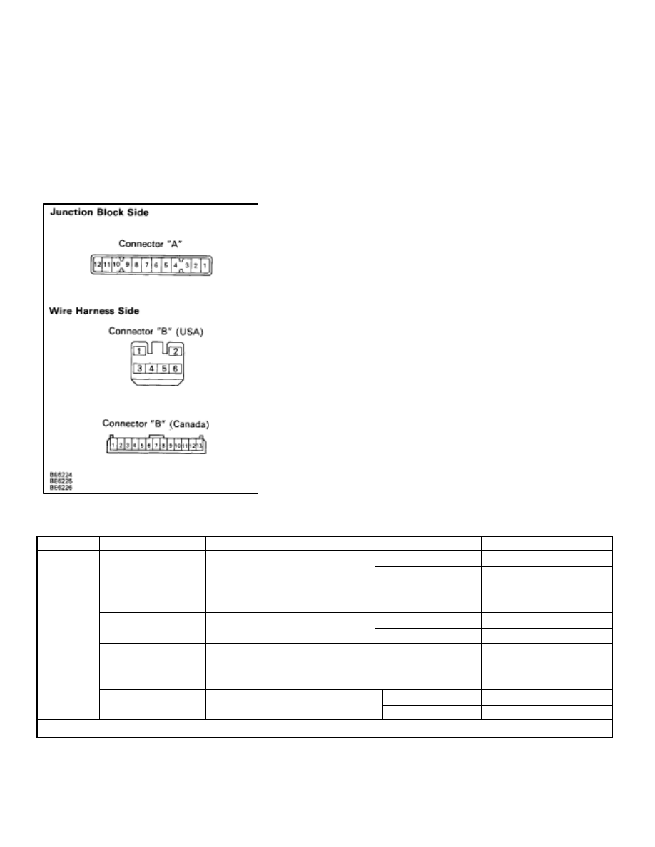
Remove the relay from junction block and inspect the con-
nector on the junction block side as shown in the chart.
Check for
Tester connection
Condition
Specified value
Continuity
A1–Ground
Driver’s or passenger’s courtesy
OFF (Door closed)
No continuity
y
A1–Ground
g
y
switch
ON (Door opened)
Continuity
A4–Ground
Passenger’s courtesy switch
OFF (Door closed)
No continuity
A4–Ground
Passenger’s courtesy switch
ON (Door opened)
Continuity
A6–Ground
Driver’s courtesy switch
OFF (Door closed)
No continuity
A6–Ground
Driver’s courtesy switch
ON (Door opened)
Continuity
A10–Ground
Constant
Continuity
Voltage
A1–Ground
Constant
*Battery voltage
g
A2–Ground
Constant
*Battery voltage
A10–Ground
Interior light switch
ON
*Battery voltage
A10–Ground
Interior light switch
OFF
No voltage
*: There is resistance because this circuit is grounded through the bulb.
If the circuit is as specified, try replacing the relay with a new
one.
If the circuit is not as specified, refer to
and inspect the circuits connected to other parts.
BE–78
–
BODY ELECTRICAL SYSTEM
Lighting System