Lexus SC300 / Lexus SC400. Manual - part 219
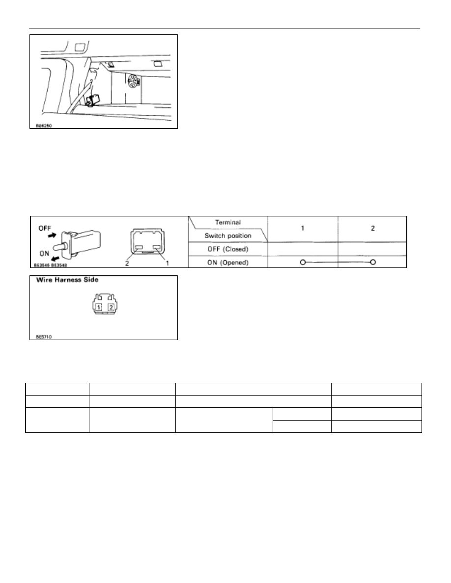
(GLOVE BOX LIGHT SWITCH)
REMOVAL AND INSTALLATION OF
GLOVE BOX LIGHT SWITCH
1.
REMOVE GLOVE BOX LIGHT SWITCH
(a) Remove glove compartment.
(See page
)
(b) Release two tabs and remove switch.
2.
INSTALL GLOVE BOX LIGHT SWITCH
For installation, follow the removal procedure in reverse.
INSPECTION OF GLOVE BOX LIGHT
SWITCH
INSPECT GLOVE BOX LIGHT SWITCH
(Continuity)
Inspect the switch continuity between terminals.
If continuity is not as specified, replace the switch.
(Switch Circuit)
Disconnect the connector from the switch and inspect the
connector on the wire harness side as shown.
Check for
Tester connection
Condition
Specified value
Continuity
2–Ground
Constant
Continuity
Voltage
1–Ground
Light control switch posi-
OFF
No voltage
Voltage
1–Ground
g
tion
TAIL or HEAD
Battery positive voltage
If the circuit is not as specified, refer to
and inspect the circuits connected to other parts.
(INTEGRATION RELAY)
(See page
(TAILLIGHT CONTROL RELAY)
(See page
BE–74
–
BODY ELECTRICAL SYSTEM
Lighting System