Lexus SC300 / Lexus SC400. Manual - part 215
 

  Index      Lexus     Lexus SC300 / Lexus SC400 - service repair manual


Search            


Content   ..  213  214  215  216   ..


Lexus SC300 / Lexus SC400. Manual - part 215


Troubleshooting

Taillight System

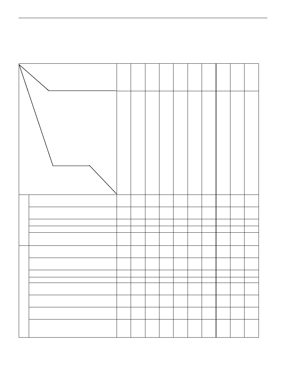
You will find the cause of troubles more easily using the table well shown below.  In this table, the numbers indi-
cate the order priority of the causes in troubles.  Check each part in the order shown.  If necessary, replace the
parts.

See page

BE–4

,20

BE–20

,57

BE–46

BE–49

BE–62

BE–79

BE–4

,20

BE–6

Trouble

Part name

T

AIL Fuse

T

aillignt Control Relay

Light Control Switch

Integration Relay

Light Failure Sensor

Door Courtesy

GAUGE Fuse

Wire Harness

Bulb

Other Parts

Taillight does not light. (Headlight does
not light.)


1

2


3

S

A

Taillight does not light. (Headlight is 
normal.)

1

2

3

4

5

US

A

Only one light does not light. (Taillight)


2

 1


U

Rear combination light does not light.


2

1

3


“Light Auto Turn–Off System” does
not operate.


1

4

3

2


Taillight does not light. (Headlight is
does not light.)


 1

2

3

Taillight does not light. (Headlight is 
normal.)

1

2

3

4

5

Only one light does not light. (Taillight)


2

1

A

Rear combination light does not light.


2

1

3

A

NADA

“Light Auto Turn–Off System” does
not operate.


1

4

2

3

CA

N

Taillight does not light with light control 
SW in TAIL

1

2

3

Taillight does not go out with light 
control SW in OFF

1

3

2

4

Headlight and Taillight do not light with
engine running and light control SW in
OFF

 2

1

3

*

1

4

*

1: Alternator L Terminal

BE–58

BODY ELECTRICAL SYSTEM

Lighting System

(STOP LIGHT SYSTEM)
DESCRIPTION – Stoplight System

The component parts of this system and their function are as shown in the following table.

ÑÑÑÑÑÑÑ

ÑÑÑÑÑÑÑ

Parts Name

ÑÑÑÑÑÑÑÑÑÑÑÑÑÑÑÑÑÑÑÑÑÑÑÑÑÑÑÑÑÑ

ÑÑÑÑÑÑÑÑÑÑÑÑÑÑÑÑÑÑÑÑÑÑÑÑÑÑÑÑÑÑ

Function

ÑÑÑÑÑÑÑ

ÑÑÑÑÑÑÑ

ÑÑÑÑÑÑÑ

Stop Light Switch

ÑÑÑÑÑÑÑÑÑÑÑÑÑÑÑÑÑÑÑÑÑÑÑÑÑÑÑÑÑÑ

ÑÑÑÑÑÑÑÑÑÑÑÑÑÑÑÑÑÑÑÑÑÑÑÑÑÑÑÑÑÑ

ÑÑÑÑÑÑÑÑÑÑÑÑÑÑÑÑÑÑÑÑÑÑÑÑÑÑÑÑÑÑ

Creates a closed circuit for current from the STOP fuse when the brake pedal is depressed,
thus turning on the stop lights.

ÑÑÑÑÑÑÑ

ÑÑÑÑÑÑÑ

ÑÑÑÑÑÑÑ

Light Failure Sen-
sor

ÑÑÑÑÑÑÑÑÑÑÑÑÑÑÑÑÑÑÑÑÑÑÑÑÑÑÑÑÑÑ

ÑÑÑÑÑÑÑÑÑÑÑÑÑÑÑÑÑÑÑÑÑÑÑÑÑÑÑÑÑÑ

ÑÑÑÑÑÑÑÑÑÑÑÑÑÑÑÑÑÑÑÑÑÑÑÑÑÑÑÑÑÑ

This sensor senses when a bulb in rear combination light is burnt out and lights up a warning
light.

PARTS LOCATION – Stoplight System

BODY ELECTRICAL SYSTEM

Lighting System

BE–59

WIRING AND CONNECTOR DIAGRAMS –
STOP LIGHT SYSTEM

BE–60

BODY ELECTRICAL SYSTEM

Lighting System

Parts Replacement – Stoplights
(Rear Combination Light)

(See page 

BE–56

 )

(High Mount Stop Light)
REPLACEMENT OF HIGH MOUNT STOP
LIGHT

1. 

REMOVE HIGH MOUNT STOP LIGHT
(a)  Disconnect negative (–) terminal from the battery.
CAUTION: Work must be started after approx. 20 se-
conds or longer from the time the ignition switch is
turned to the ”LOCK” position and negative (–) terminal
cable is disconnected from the battery.
(w/o Rear Spoiler)
(b)  Separate the woofer speaker cover from package tray

trim.

(c) Disconnect 

connector.

(d)  Remove woofer speaker cover.
(e)  Remove five screws and separate the high mount stop

light from woofer speaker cover.

(w/ Rear Spoiler)
(f)  Separate the rear spoiler from the luggage door. (See

page 

BO–106

 )

(g) Remove 

three screws and separate the high mount stop

light from rear spoiler.

2. 

INSTALL HIGH MOUNT STOP LIGHT
For installation, follow the removal procedure in reverse.

Parts Inspection– Stop Light System
(Stop Light Switch)

STOP LIGHT SWITCH

REMOVAL AND INSTALLATION OF STOP
LIGHT SWITCH

1. 

REMOVE STOP LIGHT SWITCH
(a)  Remove instrument panel subassembly cover under

No.1 and brake pedal return spring.

(b) Disconnect 

connector.

(c)  Remove a nut and switch.

2. 

ADJUSTMENT OF STOP LIGHT SWITCH
(See page 

BR–4

)

3. 

INSTALL STOP LIGHT SWITCH
For installation, follow the removal procedure in reverse.

BODY ELECTRICAL SYSTEM

Lighting System

BE–61


Content   ..  213  214  215  216   ..