Lexus SC300 / Lexus SC400. Manual - part 214


  Index      Lexus     Lexus SC300 / Lexus SC400 - service repair manual


Search            


Content   ..  212  213  214  215   ..


Lexus SC300 / Lexus SC400. Manual - part 214


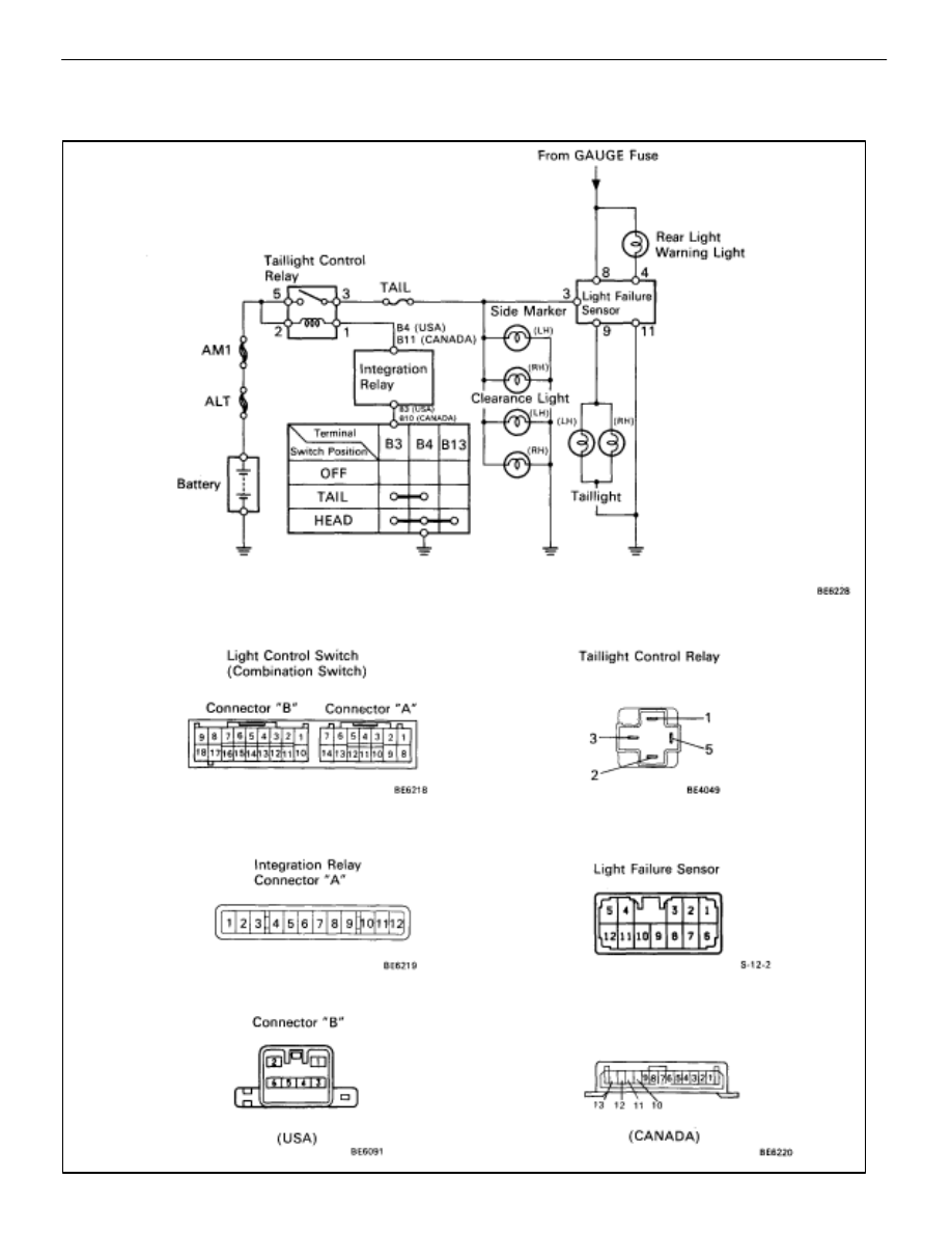
WIRING AND CONNECTOR DIAGRAMS –
Taillight System

BE–54

BODY ELECTRICAL SYSTEM

Lighting System
Parts Replacement – Taillights

(Clearance Light)
REPLACEMENT OF CLEARANCE LIGHT

(See page 

BE–37

)

HINT: Replacement of Headlight (LO–Beam).

(FRONT SIDE MARKER LIGHT)

REPLACEMENT OF FRONT SIDE
MARKER LIGHT

1. 

REMOVE FRONT SIDE MARKER LIGHT
(a)  Disconnect negative (–) terminal from the battery.
CAUTION: Work must be started after approx.20 
seconds from the time the ignition switch is turned to the
”LOCK” position and negative (–) terminal cable is 
disconnected from the battery.
(b)  Remove fender liner

BO–92

)

(c)  Remove two nuts.
(d)  Remove front side marker light from bumper.
(e) Disconnect 

connector.

2. 

INSTALL FRONT SIDE MARKER LIGHT
For installation, follow the removal procedure in reverse.

(Light Failure Sensor)

See page  

BE–62

(Integration Relay)

See page  

BE–49

(Rear Combination Assembly)

REPLACEMENT OF REAR
COMBINATION LIGHT ASSEMBLY

1. 

REMOVE REAR COMBINATION LIGHT ASSEMBLY
(a)Disconnect negative (–) terminal from the battery.
CAUTION: Work must be started after approx. 20 
seconds from the time the ignition switch is turned to the
”LOCK” position and negative (–) terminal cable is 
disconnected from the battery.

BODY ELECTRICAL SYSTEM

Lighting System

BE–55

(b) Remove the luggage compartment trim.
(c)Disconnect connector.
(d) Remove four nuts and rear combination light assembly.

2. 

INSTALL REAR COMBINATION LIGHT ASSEMBLY
Follow the removal procedure in reverse to carry out installa-
tion.

(License Plate Light)

REPLACEMENT OF LICENSE PLATE
LIGHT

1. 

REMOVE LICENSE PLATE LIGHT
(a) Disconnect negative (–) terminal from the battery.
CAUTION: Work must be started after. 20 seconds from
the time the ignition switch is turned to the ”LOCK” posi-
tion and negative (–) terminal cable is disconnected from
the battery.
(b) Remove the rear bumper.
(c) Disconnect connector.
(d) Remove three screws and the license plate light.

2. 

INSTALL LICENSE PLATE LIGHT
Follow the removal procedure in reverse to carry out 
installation.

BE–56

BODY ELECTRICAL SYSTEM

Lighting System

Parts Inspection – Taillights

(Combination Switch Assembly)

(See page 

BE–46

HINT:     Inspect light control switch.

(Taillight Control Relay)
REMOVAL AND INSTALLATION OF
TAILLIGHT CONTROL RELAY

(See page 

BE–16

)

INSPECTION OF TAILLIGHT CONTROL
RELAY

INSPECT TAILLIGHT CONTROL RELAY

(Continuity)
Inspect relay continuity between terminals.

If continuity is not as specified, replace the relay.
(Relay Circuit)
(See page 

BE–20

)

BODY ELECTRICAL SYSTEM

Lighting System

BE–57


Content   ..  212  213  214  215   ..