Lexus SC300 / Lexus SC400. Manual - part 201
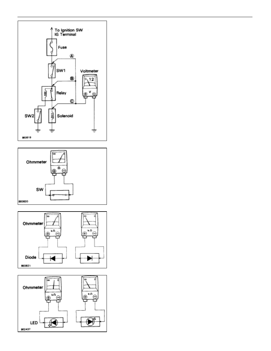
Check for Voltage
(a) Establish conditions in which voltage is present at the
check point.
Example:
(A)–Ignition SW on
(B)–Ignition SW and SW 1 on
(C)–Ignition SW, SW 1 and Relay on (SW 2 off)
(b) Using a voltmeter, connect the negative (–) lead to a
good ground point or negative (–) battery terminal and
the positive (+) lead to the connector or component
terminal. This check can be done with a test bulb instead
of a voltmeter.
Check for Continuity and Resistance
(a) Disconnect the battery terminal or wire so there is no
voltage between the check points.
(b) Connect the two leads of an ohmmeter to each of the
check points.
If the circuit has diodes, reverse the two leads and check
again.
When contacting the negative (–) lead to the diode positive
(+) side and the positive (+) lead to the negative (–) side,
there should be continuity. When contacting the two leads in
reverse, there should be no continuity.
HINT: Specifications may vary depending on the type of tes-
ter, so refer to the tester’s instruction manual before perform-
ing the inspection.
Check LED (Light Emitting Diode) in the same manner as that
for diodes.
HINT:
•
Use a tester with a power source of 3 V or greater to
overcome the circuit resistance.
•
If a suitable tester is not available, apply battery voltage
and check that the LED lights up.
–
BODY ELECTRICAL SYSTEM
General Information
BE–5