Lexus SC300 / Lexus SC400. Manual - part 199
 

  Index      Lexus     Lexus SC300 / Lexus SC400 - service repair manual


Search            


Content   ..  197  198  199  200   ..


Lexus SC300 / Lexus SC400. Manual - part 199


NG

OK

INSPECTION PROCEDURE

1

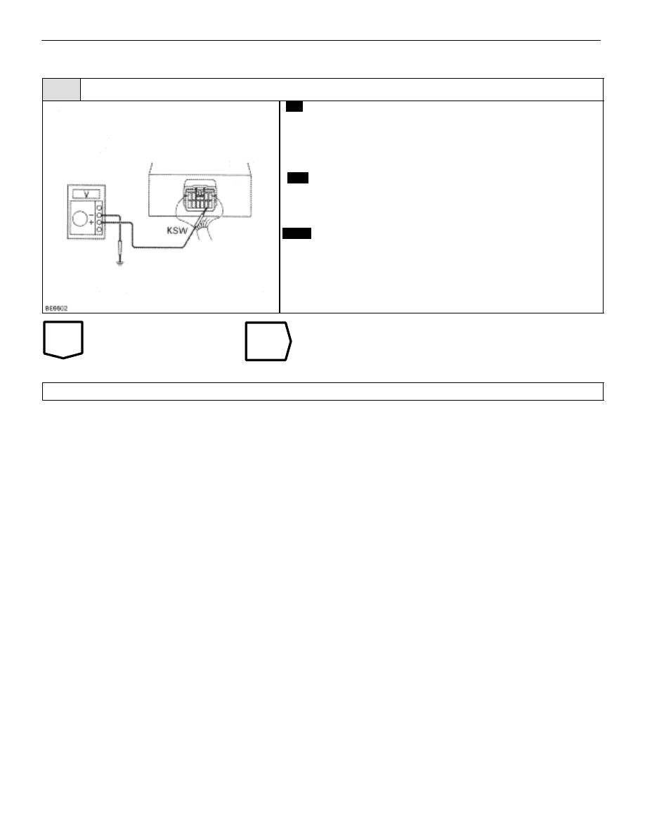
Check voltage between terminal KSW of ECU connector and body ground.

C

OK

P

1.

Remove the rear seat and RH quarter trim panel.

2.

Remove the ECU.

3.

Key plate is not inserted in the key cylinder.

Measure voltage between terminal KSW of ECU con-
nector and body ground, when key plate is not inserted
in the key cylinder.

Voltage:

10 – 14 V

Proceed to next circuit inspection shown on matrix chart
(See page 

BE–454

).

Check and repair harness and connector between ECU and key unlock warning switch.

BODY ELECTRICAL SYSTEM

Wireless Door Lock Control System

BE–469

WIRING DIAGRAM

Door Open Detection Switch Circuit

CIRCUIT DESCRIPTION

The door open detection switch comes ON when the door is opened and goes OFF when the door is closed.
Furthermore the door open detection switch circuit has terminal +B connected inside the theft deterrent and door
lock ECU, battery positive voltage is applied to terminal DSWD of the wireless door lock ECU when all doors
are closed, i.e., when the door open detection switch of all doors are OFF.

DIAGNOSTIC CHART

DIAGNOSTIC CHART

NG

OK

Check open door warning light

circuit (See page 

BE–118

).

Check operation of open door warning
light

Check voltage between terminal DSWD
of ECU connector and body ground.

Proceed to next circuit inspec-
tion show on matrix chart (See

page 

BE–454

).

Check and repair harness and connector
between ECU and door open detection
switch.;

1

2

BE–470

BODY ELECTRICAL SYSTEM

Wireless Door Lock Control System

OK

NG

NG

OK

INSPECTION PROCEDURE

1

Check operation of open door warning light.

Check that open door warning light comes on when each door is opened, and goes off when all doors
are closed.

C

Check open door warning light circuit (See page

BE–118

).

2

Check voltage between terminal DSWD of ECU connector and body ground.

C

OK

P

1.

Remove the rear seat and RH quarter trim panel.

2.

Remove the ECU.

3.

Wireless door lock main switch on.

Measure voltage between terminal DSWD of ECU con-
nector and body ground, when all doors are closed.

Voltage:

10 – 14 V

Proceed to next circuit inspection shown on matrix chart
(See page 

BE–454

).

Check and repair harness and connector between ECU and door open detection switch.

BODY ELECTRICAL SYSTEM

Wireless Door Lock Control System

BE–471

–MEMO–

BE–472

BODY ELECTRICAL SYSTEM

Wireless Door Lock Control System


Content   ..  197  198  199  200   ..