Lexus SC300 / Lexus SC400. Manual - part 149
 

  Index      Lexus     Lexus SC300 / Lexus SC400 - service repair manual


Search            


Content   ..  147  148  149  150   ..


Lexus SC300 / Lexus SC400. Manual - part 149


(Circuit)
Disconnect the control panel connector and inspect the con-
nector on wire harness side as shown.

Check for

Tester connection

Condition

Specified value

Voltage

2–Ground

Light control switch position

TAIL or HEAD

Battery voltage

OFF

No voltage

If circuit is not as specified, refer to 

BE–199

, 201, 203 wiring

diagrams and inspect the circuits connected to other parts.

(Radio Receiver Assembly)
REMOVAL AND INSTALLATION OF
RADIO RECEIVER ASSEMBLY

(See page 

BE–112

)

INSPECTION OF RADIO RECEIVER
ASSEMBLY

INSPECT RADIO RECEIVER ASSEMBLY

(Circuit)
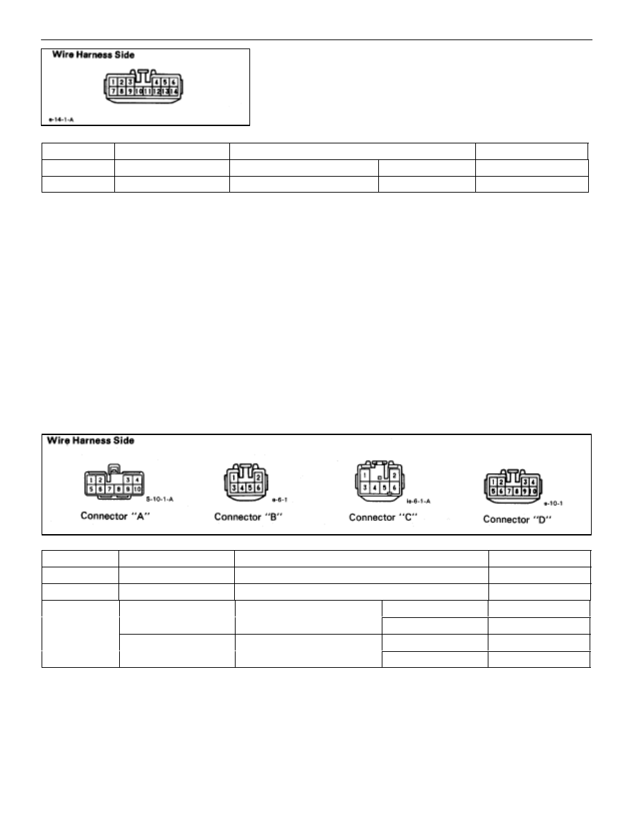
Disconnect the connectors from the radio receiver assembly.
And inspect the connector on the wire harness side as
shown.

(without CD player)

Check for

Tester connection

Condition

Specified value

Continuity

A7–Ground

Constant

Continuity

Voltage

A4–Ground

Constant

Battery voltage

Voltage

A3–Ground

Ignition switch position

ACC or ON

Battery voltage

g

LOCK

No voltage

A10–Ground

Light control switch position

TAIL or HEAD

Battery voltage

g

OFF

No voltage

If circuit is not as specified, refer to 

BE–199

 wiring diagrams

and inspect the circuits connected to other parts.

BODY ELECTRICAL SYSTEM

Audio System

BE–207

(With CD player)

Check for

Tester connection

Condition

Specified value

Voltage

A4–Ground

Constant

Battery voltage

A3–Ground

Ignition switch position

ACC or ON

Battery voltage

g

LOCK

No voltage

A2–Ground

Light control switch

TAIL or HEAD

Battery voltage

g

position

OFF

No voltage

If circuit is not as specified, refer to  

BE–201

, 203 wiring dia-

grams and inspect the circuits connected to other parts.
HINT: Check the wire harness between radio receiver assem-
bly and the CD auto changer, between radio receiver assem-
bly and power amplifier, in accordance with the wiring dia-
grams in 

BE–201

, 203.

(Front Door Speaker)

REMOVAL AND INSTALLATION OF
FRONT DOOR SPEAKER

(See page 

BO–35

)

(Tweeter)

REMOVAL AND INSTALLATION OF
TWEETER

(See page 

BO–34

)

(Rear Speaker)

REMOVAL AND INSTALLATION OF
REAR SPEAKER

1. 

REMOVE REAR SPEAKER
(a)  Remove the package tray trim.
HINT: (See page 

BO–124

)

(b)  Remove eight bolts.
(c)  Disconnect connectors and remove the rear speaker.

2. 

INSTALL REAR SPEAKER
For installation, follow the removal procedure in reverse.

BE–208

BODY ELECTRICAL SYSTEM

Audio System

(Woofer)
REMOVAL AND INSTALLATION OF
WOOFER

1. REMOVE 

WOOFER

(a)  Remove woofer cover together with high mount stop

light.

(b)  Remove four bolts.
(c)  Disconnect connector and remove woofer.

2. INSTALL 

WOOFER

For installation follow the removal procedure in reverse.

(Woofer Amplifier)
REMOVAL AND INSTALLATION OF
WOOFER AMPLIFIER

(without CD player)
1. 

REMOVE WOOFER AMPLIFIER
(a)  Remove the RH side cover.
(b)  Disconnect the connector and remove three nuts and

the woofer amplifier with the bracket.

(c)  Remove four bolts and the woofer amplifier.

2. 

INSTALL WOOFER AMPLIFIER
For installation, follow the removal procedure in reverse.

(with CD player–Pioneer)
1. 

REMOVE WOOFER AMPLIFIER
(a)  Remove the package tray trim.
HINT: (See page 

BO–124

)

(b)  Remove four bolts.

BODY ELECTRICAL SYSTEM

Audio System

BE–209

(c)  Disconnect the connector and remove the woofer

amplifier.

2. 

INSTALL WOOFER AMPLIFIER
For installation, follow the removal procedure in reverse.

INSPECTION OF WOOFER AMPLIFIER

INSPECT WOOFER AMPLIFIER

(Circuit)
Disconnect the connector from woofer amplifier and inspect
the connector on the wire harness side as shown.

Check for

Tester connection

Condition

Specified value

Continuity

7–Ground

Constant

Continuity

Voltage

3–Ground

Constant

Battery voltage

4–Ground

Ignition switch position

ACC or ON

Battery voltage

6–Ground

g

LOCK

No voltage

If circuit is not as specified, refer to 

BE–201

 wiring diagrams

and inspect the circuits connected to other parts.

(Power Amplifier)
REMOVAL AND INSTALLATION OF
POWER AMPLIFIER

(Pioneer)

1. 

REMOVE POWER AMPLIFIER
(a)  Remove the RH side cover.
(b)  Remove the CD auto changer (See page 

BE–212

).

(c)  Disconnect two connectors and remove three nuts and

the power amplifier with the bracket.

(d)  Remove four bolts and the power amplifier.

2. 

INSTALL POWER AMPLIFIER
For installation, follow the removal procedure in reverse.

BE–210

BODY ELECTRICAL SYSTEM

Audio System


Content   ..  147  148  149  150   ..