Lexus SC300 / Lexus SC400. Manual - part 136
 

  Index      Lexus     Lexus SC300 / Lexus SC400 - service repair manual


Search            


Content   ..  134  135  136  137   ..


Lexus SC300 / Lexus SC400. Manual - part 136


Parts Inspection
(Power Window Master Switch)

REMOVAL AND INSTALLATION OF
POWER WINDOW MASTER SWITCH

(See page 

BO–33

)

INSPECTION OF POWER WINDOW
MASTER SWITCH

INSPECT POWER WINDOW MASTER SWITCH

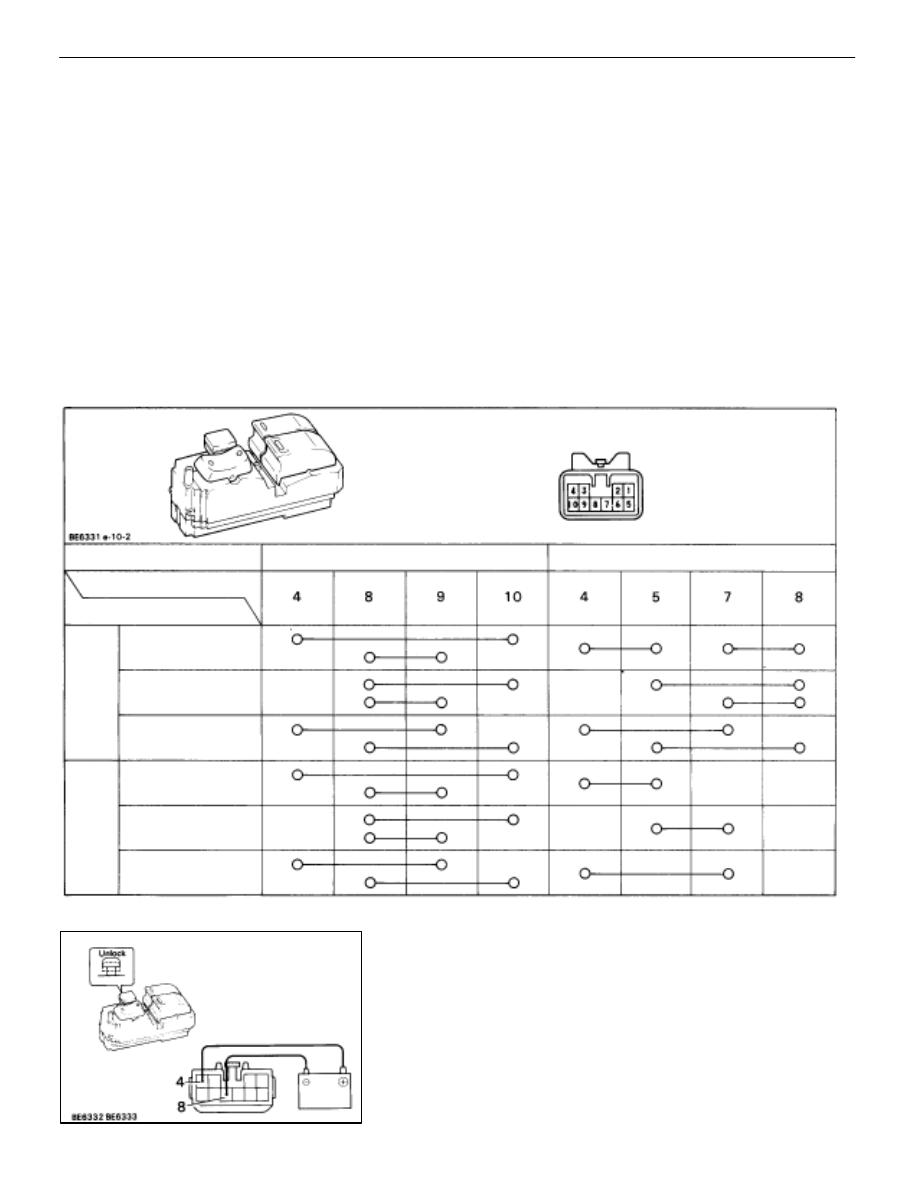
(Continuity)
Inspect the switch continuity between terminals.

Window operation

Driver’s

Passenger’s

Terminal

Switch position

UP

OFF

DOWN

UP

OFF

DOWN

Window Unlock

Window Lock

If continuity is not as specified, replace the master siwtch.

(Illumination)
(a)  Set the window lock switch to the unlock position.
(b) Connect 

the positive (+) lead from the battery to terminal

4 and the negative (–) lead to terminal 8, check that all
the illuminations light up.

BODY ELECTRICAL SYSTEM

Power Window Control System

BE–149

(c)  Set the window lock switch to the lock position, check

that all the passenger ’s power window switch
illuminations go out.

If operation is not as specified, replace the master switch.

(One Touch Power Window System/Current of Circuit)
Inspection using an ammeter.
(a)  Disconnect the connector from the master switch.
(b) Connect the positive (+) lead from the ammeter to

terminal 9 on the wire harness side connector and the
negative (–) lead to negative terminal of the battery.

(c) Connect 

the positive (+) lead from the battery to terminal

10 on the wire harness side connector.

(d)  As the window goes down, check that the current flow

is approximately 7 amperes.

(e)  Check that the current increases approximately 14.5

amperes or more when the window stops going down.

HINT: The circuit breaker opens some 4–40 seconds after the
window stops going down, so that check must be made be-
fore the circuit breaker operates.
If the operation is as specified, replace the master switch.

Inspection using an ammeter with a current–measuring
probe.
(a)  Remove the master switch with connector connected.
(b)  Attach a current–measuring probe to terminal 4 of the

wire harness.

(c)  Turn the ignition switch ON and set the power window

switch in the down position.

(d)  As the window goes down, check that the current flow

is approximately 7 amperes.

(e)  Check that the current increases approximately 14.5

amperes or more when the window stops going down.

HINT: The circuit breaker opens some 4–40 seconds after the
window stops going down, so that check must be made be-
fore the circuit breaker operates.
If operation is as specified, replace the master switch.

BE–150

BODY ELECTRICAL SYSTEM

Power Window Control System

(Switch Circuit)
Disconnect the connector from the master switch and inspect
the connector on the wire harness side as shown.

Check for

Tester connection

Condition

Specified value

Voltage

9–Ground

Ignition switch turned to ON

Battery voltage

Continuity

8–Ground

Constant

Continuity

If the circuit is not as specified, refer to 

BE–148

 wiring dia-

gram and inspect the circuits connected to other parts.

(Power Window Switch)
REMOVAL AND INSTALLATION OF
POWER WINDOW SWITCH

(See page 

BO–33

)

INSPECTION OF POWER WINDOW
SWITCH

INSPECT POWER WINDOW SWITCH

(Switch Continuity)
Inspect switch continuity between terminals.

Terminal

Switch

position

UP

OFF

DOWN

If continuity is not as specified, replace the switch.

(Switch Circuit)
Disconnect the connector from the switch and inspect the
connector on the wire harness side as shown.

Check for

Tester connection

Condition

Specified value

Voltage

2–Ground

Ignition switch ON and

DOWN

Battery positive voltage

g

g

master switch position

OFF

No voltage

3–Ground

Ignition switch ON

Battery positive voltage

4–Ground

Ignition switch ON and 

UP

Battery positive voltage

g

master switch position

OFF

No voltage

If the circuit is not as specified, refer to 

BE–148

 wiring dia-

gram and inspect the circuits connected to other parts.

BODY ELECTRICAL SYSTEM

Power Window

BE–151

(Power Window Main Relay)
REMOVAL AND INSTALLATION OF
POWER WINDOW MAIN RELAY

(See page 

BE–16

)

INSPECTION OF POWER WINDOW MAIN
RELAY

INSPECT POWER WINDOW MAIN RELAY

(Continuity)
Inspect relay continuity between terminals.

Terminal

Condition

Constant

Apply battery voltage

to terminals 1 and 2.

If continuity is not as specified, replace the relay.

(Relay Circuit)
(See page 

BE–20

)

(Power Window Motor)
REMOVAL AND INSTALLATION OF
POWER WINDOW MOTOR

1. 

REMOVE POWER WINDOW MOTOR
(a)  Remove window regulator.

(See page 

BO–35

)

2. 

INSTALL POWER WINDOW MOTOR
For installation follow the removal procedure in reverse.

INSPECTION OF POWER WINDOW
MOTOR

INSPECT POWER WINDOW MOTOR

(Left Side Door Motor/Motor Operation)
(a) Connect 

the positive (+) lead from the battery to terminal

1 and the negative (–) lead to terminal 2, check that the
motor turns counterclockwise.

(b)  Reverse the polarity, check that the motor turns

clockwise.

If operation is not as specified, replace the motor.

BE–152

BODY ELECTRICAL SYSTEM

Power Window Control System


Content   ..  134  135  136  137   ..