Lexus SC300 / Lexus SC400. Manual - part 18
 

  Index      Lexus     Lexus SC300 / Lexus SC400 - service repair manual


Search            


Content   ..  16  17  18  19   ..


Lexus SC300 / Lexus SC400. Manual - part 18


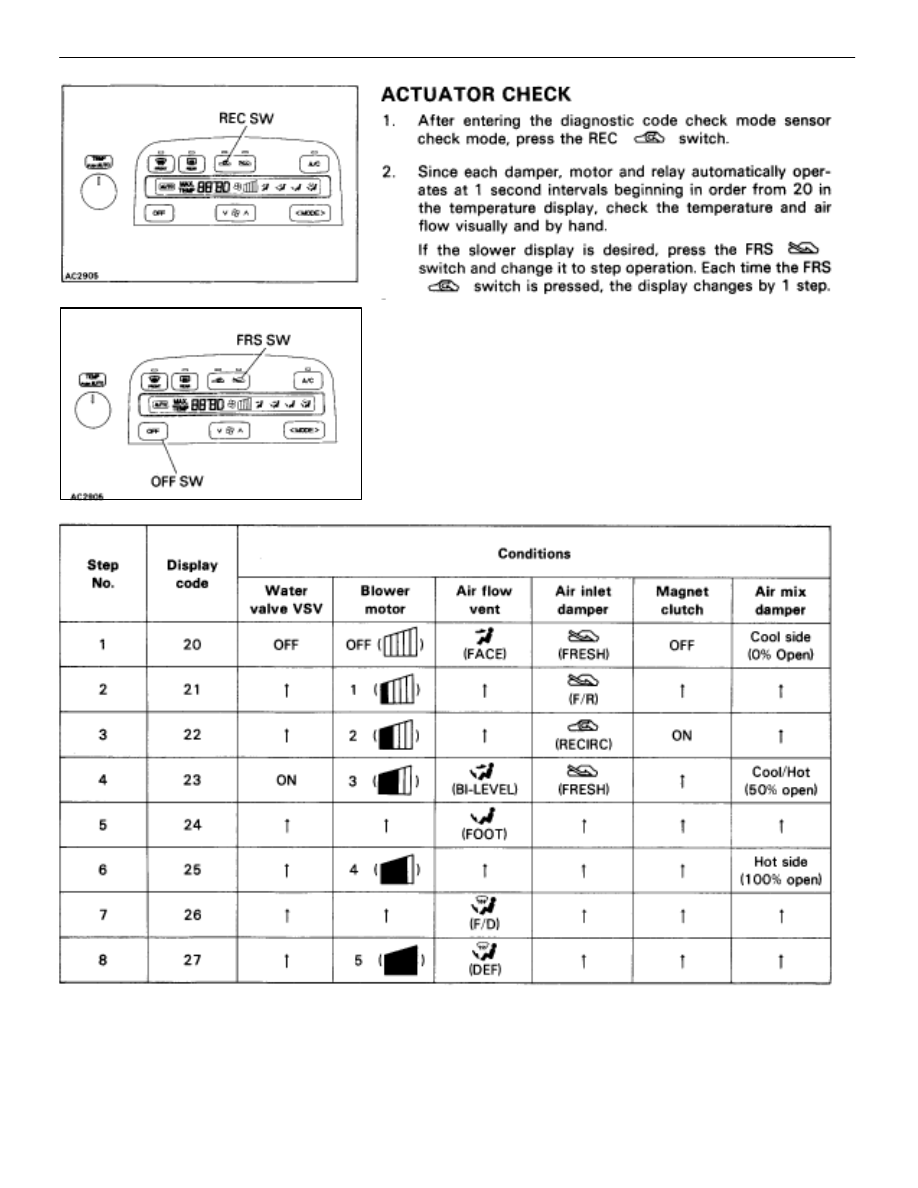
HINT:

The buzzer sounds when the display code changes.

Codes are displayed in order from the smaller to the
larger numbers.

To cancel the check mode, press the OFF switch.

AC–30

AIR CONDITIONING SYSTEM

Troubleshooting

A14–1

A14–2

A14–3

A14–4

A14–5

A14–6

A14–7

A14–8

A14–9

A14–10

A14–11

A14–12

A14–13

A14–14

A12–1

A14–15

A12–2

A12–3

A12–4

A12–5

A12–6

A12–7

A12–8

A12–9

A12–10

A13–25

A13–24

A13–23

A13–22

A13–21

A13–20

A13–19

A13–18

A13–17

A13–16

A13–15

A13–14

A13–13

A13–12

A13–11

A13–10

A13–9

A13–8

A13–7

A13–6

A13–5

A13–

A13–4

A13–3

A13–2

A13–1

TERMINALS OF ECU

AIR CONDITIONING SYSTEM

Troubleshooting

AC–31

STANDARD VALUE OF ECU TERMINAL

Terminals

Symbols

WiringColor

Condition

StandardValue

A14–1


A14–7

B


E

R


W–B

IG OFF

10 ~ 14 V

A14–2


A14–3

MH


MC

V


R–Y

IG OFF

13 ~ 19 


A14–4


A14–5

MFRS


MREC

G


G–R

IG OFF

13 ~ 19 


A14–6


A14–7

IG+


E

R–L


W–B

IG ON

10 ~ 14 V

             Body

 A14–7


            Ground

      Body

E


     Ground

           Body

W–B


          Ground

Always

Below 1 


A14–8


A14–9

FACE


DEF

W


Y–L

IG OFF

13 ~ 19 


A14–15


A14–7

ACC


E

L–R


W–B

Turn ignition switch ACC

10 ~ 14 V

A12–2


A14–7

REOST


E

W–G


W–B

IG ON and turn headlight control SW 
to TAIL position.
Turn Rheostat volume from most
right to left position.

Most
        : 0 ~ 14 V
Right


Most
        : 10 ~ 14 V
Left

A12 3


A14 7

WV


E

B Y


W B

Start
the

                                           MAX
Temp. Control Switch:
                                           COLD

Below 1 V

A12–3


A14–7

WV


E

B–Y


W–B

the
en-
gine

                                           MAX
Temp. Control Switch:
                                           HOT

10 ~ 14 V

A12 4


A14 7

MGC


E

L R


W B

Start the
engine and

A/C switch ON

Below 1 V

A12–4


A14–7

MGC


E

L–R


W–B

engine and
push AUTO
SW

A/C switch OFF

10 ~ 14 V

A12 5


A14 7

TC


E

L


W B

IG ON
H L C SW

Rheostat Most
             :
Volume Right

Below 1 V

A12–5


A14–7

TC


E

L


W–B

H.L.C. SW
: TAIL position

Rheostat Turn
             :
Volume Left

10 ~ 14 V

A12–6


A14–7

TAIL


E

G


W–B

Turn the light control switch to TAILposition

10 ~ 14 V

A12–7A14–7

LVE

YW–B

IG ON

Push blower SW to change
the blower speed from 1 to
10.

Speed 1: 10 ~ 14 V


Speed 10: Below 2 V

A12–8


A14–7

BLR


E

B–R


W–B

IG ON Turn the blower motor

Below 1.5 V

A12–9


A14–7

HR


E

L–W


W–B

IG ON

Turn the blower motor

Below 1 V

IG ON

Don’t turn the blower motor

10 ~ 14 V

A12 10


A14 7

RDFGR


E

R Y


W B

IG ON

Rear defogger switch ON

Below 1 V

A12–10


A14–7

RDFGR


E

R–Y


W–B

IG ON

Rear defogger switch OFF

10 ~ 14 V

A13–1


A14–7

IGN


E


BW–B

Start the engine

10 ~ 14 V

AC–32

AIR CONDITIONING SYSTEM

Troubleshooting

AIR CONDITIONING SYSTEM

Troubleshooting

AC–33


Content   ..  16  17  18  19   ..