Lexus SC300 / Lexus SC400. Manual - part 17
 

  Index      Lexus     Lexus SC300 / Lexus SC400 - service repair manual


Search            


Content   ..  15  16  17  18   ..


Lexus SC300 / Lexus SC400. Manual - part 17


DIAGNOSIS SYSTEM

Warning for A/C compressor lock

If compressor lock occurs during air conditioner operation, the
( A/C )  switch indicator on the air conditioner control assembly
starts blinking to warn the driver.
When this occurs, check for compressor lock (code 22) using diag-
nostic code check then proceed to inspect the circuit or the com-
ponent.
Compressor lock sensor circuit  page 

AC–54

.

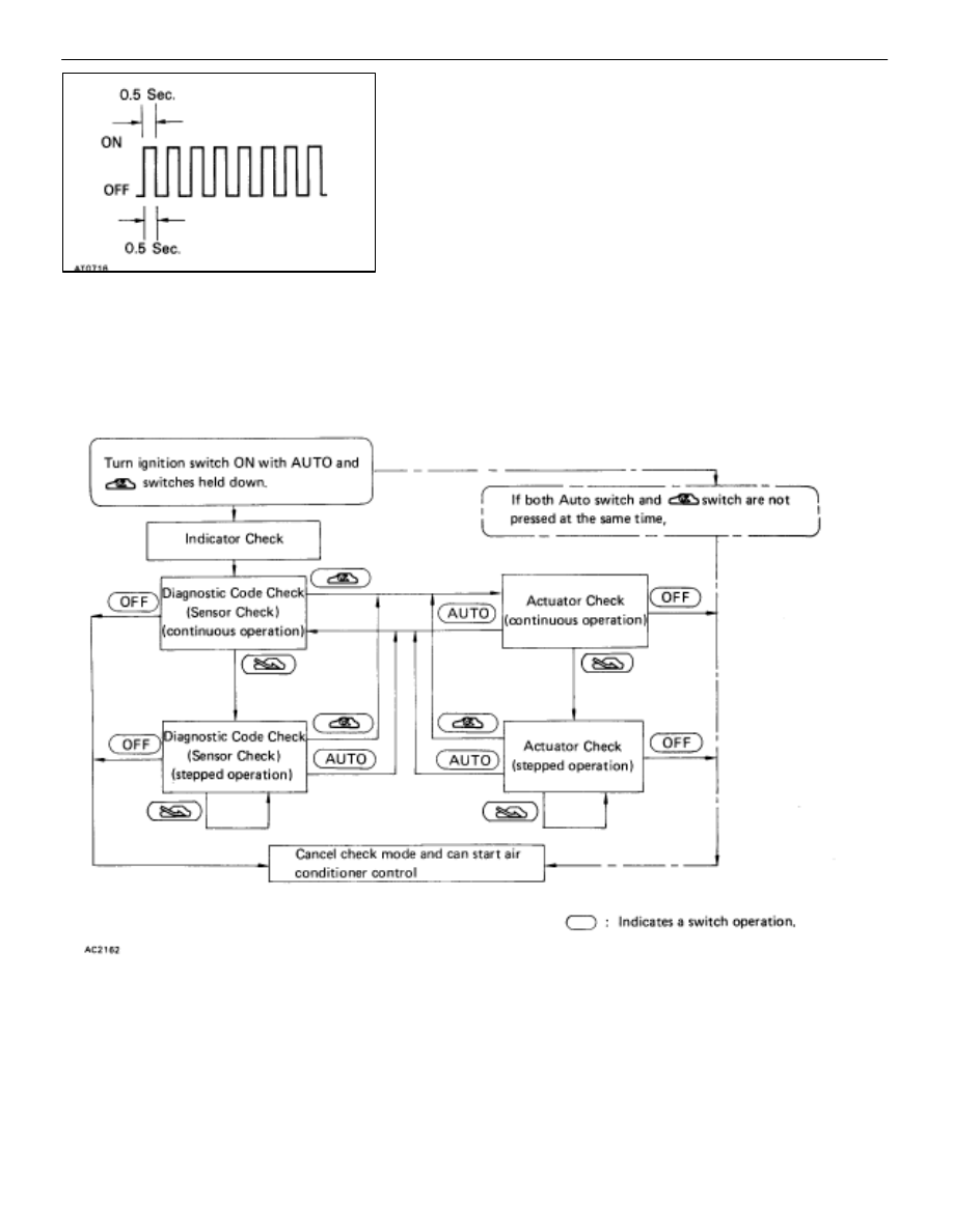
LIST OF OPERATION METHODS

By operating each of the air conditioner control switches as shown in the diagram below, it is possible to enter
the diagnosis check mode.

AC–26

AIR CONDITIONING SYSTEM

Troubleshooting

INDICATOR

1. 

Turn the ignition switch on while pressing the ari 

conditioner control 

 switch and REC swich 


simultaneously.

2. 

Check that all the indicators light up and go off at 1 second
intervals 4 times in succession.

3. 

Check that the buzzer sounds when the indicators light up in
2.
HINT:

After the indicator check is ended, the diagnostic code
check begins automatically.

Press the OFF switch when desiring to cancel the check
mode.

DIAGNOSTIC CODE CHECK (SENSOR
CHECK)

1.  Perform an indicator check. After the indicator check is

completed, the system enters the diagnostic code check
mode automatically.

2. 

Read the code displayed on the panel. Refer to the list of
codes on page 

AC–28

 when reading the codes. (Codes are

output at the temperature display.)

If the slower display ped is desired, press the FRS 
switch and change it to stepped operation. Each time the

FRS 

 switch is pressed, the display changes by 1 step.

HINT:

If the buzzer sounds when a code is being read, it means
the trouble indicated by that code continues to occur.

If the buzzer does not sound when a code is being read,
it means the trouble indicated by that code occurred ear-
lier (such as poor connector contacts, etc.)

CLEARING DIAGNOSTIC CODES

1. 

Pull out the DOME fuse in Relay Block No. 2 for 10 sec. or
longer to clear the memory of diagnostic codes.

2.  After reinserting the fuse, check that the normal code is

output.

AIR CONDITIONING SYSTEM

Troubleshooting

AC–27

DIAGNOSTIC CODE CHART

If a malfunction code is displayed during the diagnostic code check (sensor check), check the circuit listed for
that code in the table below (Proceed to the page given for that circuit.)

Code No.

Diag. Code Detecting Condition

00


  Normal

11*

1


 Open or short in room temperature sensor circuit.

12


 Open or short in ambient temperature sensor circuit.

13


 Open or short in evaporator temperature sensor circuit.

14*

2


 Open or short in water temperature sensor circuit.

21*

3


 Open in solar sensor circuit.

21*

3


 Short in solar sensor circuit.

22*

4


 All conditions below are detected for 3 secs. or more.


 (a) Engine rpm : 450 rpm or more.


 (b) Ratio between engine and compressor rpm deviates 20% or more in comparison to normal
       operation.

23


 Open in pressure sensor circuit.


 Abnormal refrigerant pressure   below 206 kPa (2.1 kgf/cm, 30 psi)

                                      over 2,650 kPa (27 kgf/cm, 385 psi)

31


 Short to ground or power source circuit in Air Mix Damper position sensor circuit.

32


 Short to ground or power source circuit in Air Inlet Damper position sensor circuit.

33


 Short to ground or power source circuit in Air Outlet Damper position sensor circuit.

41


 Air mix damper position sensor value does not change even if ECU operates air mix servomotor.

42


 Air inlet damper position sensor value does not change even if ECU operates air inlet servomotor.

43


 Air outlet damper position sensor value does not change even if ECU operates air outlet 
  servomotor.

HINT: *1  If the room temp. is approx. –20

°

C (–4

°

F) or lower, code 11 may be output even though the system

is normal.

*2  If the ambient temperature is approx. –50

°

C (–58

°

F) or lower, a malfunction code may be output


even though the system is normal.

*3  If the check is being performed in a dark place, diagnostic code 21 (solar sensor circuit abnormal) 

could be displayed.
In this case, perform diagnostic code check again while shining a light, such as an inspection light,
on the solar sensor.
If code 21 is still displayed, there could be trouble in the solar sensor circuit

AC–28

AIR CONDITIONING SYSTEM

Troubleshooting

Trouble Area

Memory*

5

See page

                                                                 –


 Room temp. Sensor


 Harness or connector between room temp. sensor and A/C control assembly


 A/C control assembly

O

(8.5 min. or more)

AC–44


 Ambient temp. sensor


 Harness or connector between ambient temp. sensor and A/C control assembly


 A/C control assembly

O

(8.5 min. or more)

AC–46


 Evaporator temp. sensor


 Harness or connector between evaporator temp. sensor and A/C control

    assembly        

A/C control assembly

O

(8.5 min. or more)

AC–48


 Water temp. sensor


 Harness or connector between water temp. sensor and A/C control assembly


 A/C control assembly

O

(8.5 min. or more)

AC–50


 Solar sensor

H

b

d A/C

l

bl

AC 52

 Solar sensor


 Harness or connector between sensor and A/C control assembly


A/C control assembly

O

AC–52


 A/C control assembly

O

(8.5 min. or more)


 Compressor drive belt   

Compressor lock sensor   

Compressor


 Harness and connector between A/C control assembly and compressor,


  compressor lock sensor


 A/C control assembly

AC–54


 Pressure switch


 Harness or connector between pressure switch and A/C control assembly


 Refrigerant pipe line


 A/C control assembly

AC–56


 Air mix damper position sensor  A/C control assembly


 Harness or connector between air mix damper position sensor and 
  A/C control assembly

O

(1 min. or more)

AC–58


 Air inlet damper position sensor   

A/C control assembly


 Harness or connector between air inlet damper position sensor and 
  A/C control assembly

O

(1 min. or more)

AC–62


 Air outlet damper position sensor   

A/C control assembly


 Harness or connector between air outlet damper position sensor and 
  A/C control assembly

O

(1 min. or more)

AC–66


 Air mix servomotor   

Air mix damper position sensor


 Harness and connector between A/C control assembly and air mix position sensor


 Harness and connector between A/C control assembly and air mix servomotor.

O

(15 secs. or more)

AC–58
AC–60


 Air inlet servomotor   

Air inlet damper position sensor


 Harness and connector between A/C control assembly and air inlet position sensor.


 Harness and connector between A/C control assembly and air inlet servomotor.

O

(15 secs. or more)

AC–62
AC–64


 Air outlet servomotor   

Air outlet damper position sensor


 Harness and connector between A/C control assembly and air outlet position
  sensor.


 Harness and connector between A/C control assembly and air outlet servomotor.


 A/C control assembly

O

(15 secs. or more)

AC–66
AC–68

AIR CONDITIONING SYSTEM

Troubleshooting

AC–29


Content   ..  15  16  17  18   ..