Lexus ES300 (1997 year). Manual - part 132
BE05V–01
N13473
1
2
3
4
5
6
7
8
9
10
N21376
Wire Harness Side
1 2 3 4 5 6 7 8 9 10
h–10–1–c
BE–134
–
BODY ELECTRICAL
POWER MIRROR CONTROL SYSTEM
1518
1997 LEXUS ES300 (RM511U)
INSPECTION
1.
Master switch left side:
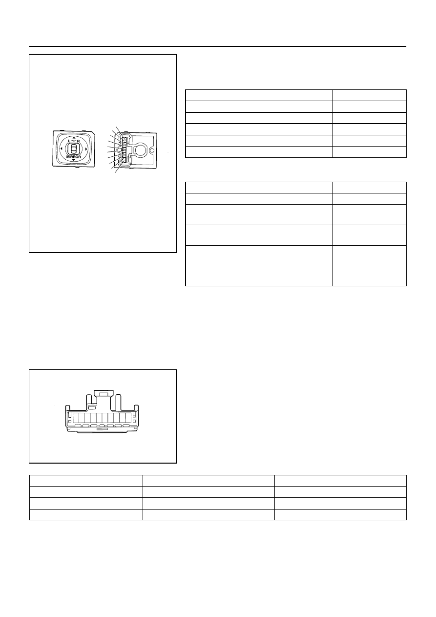
INSPECT MIRROR SWITCH CONTINUITY
Switch position
Tester connection
Specified condition
OFF
–
No continuity
UP
3 – 4 7 – 8
Continuity
DOWN
3 – 8 4 – 7
Continuity
LEFT
4 – 9 7 – 8
Continuity
RIGHT
4 – 7 8 – 9
Continuity
2.
Master switch right side:
INSPECT MIRROR SWITCH CONTINUITY
Switch position
Tester connection
Specified condition
OFF
–
No continuity
UP
2 – 4
1 – 7 – 8
Continuity
DOWN
4 – 7
1 – 2 – 8
Continuity
LEFT
4 – 10
1 – 7 – 8
Continuity
RIGHT
4 – 7
1 – 8 – 10
Continuity
If continuity is not as specified, replace the switch.
If continuity is as specified. inspect the switch circuit.
3.
INSPECT MIRROR SWITCH CIRCUIT
Disconnect the connector from the switch and inspect the con-
nector on the wire harness side.
Tester connection
Condition
Specified condition
8 – Ground
Constant
Continuity
4 – Ground
Ignition switch position LOCK
No voltage
4 – Ground
Ignition switch position ACC or ON
Battery positive voltage
If the circuit is not as specified, inspect the circuits connected
to other parts.