Lexus ES300 (1997 year). Manual - part 130
 

  Index      Lexus     Lexus ES300 - service repair manual 1997 year


Search            


Content   ..  128  129  130  131   ..


Lexus ES300 (1997 year). Manual - part 130


N21180

ON

OFF

No.1
Limit Switch

No.2
Limit Switch

1

2

3

4

5

6

N21553

Wire Harness Side

1

2

3 4
5 6

g–6–1–B

N21644

within
10 to 60
seconds

BE–126

BODY ELECTRICAL

SLIDING ROOF SYSTEM

1510

1997 LEXUS ES300   (RM511U)

3.

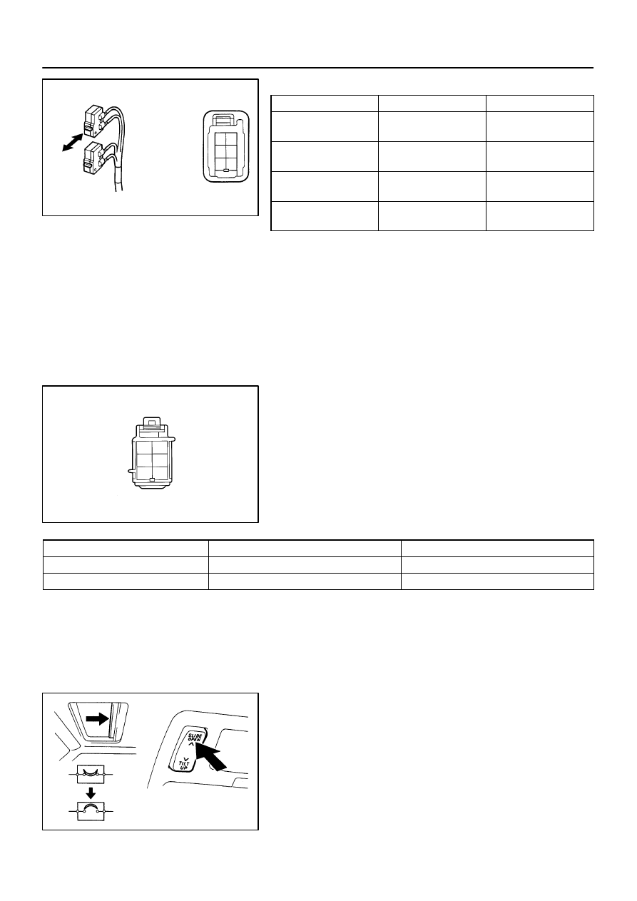
INSPECT SLIDING ROOF LIMIT SWITCH CONTINUITY

Switch position

Tester connection

Specified  condition

No.1 limit switch OFF

(SW pin released)

4 – 5

No continuity

No.1 limit switch ON

(SW pin pushed in)

4 – 5

Continuity

No.2 limit switch OFF

(SW pin released)

4 – 6

No continuity

No.2 limit switch ON

(SW pin pushed in)

4 – 6

Continuity

If continuity is not as specified, replace the switch.

4.

INSPECT SLIDING ROOF MOTOR AND LIMIT SWITCH
CIRCUIT

Disconnect the connector from the limit switch and inspect the
connector on the wire harness side.

Tester connection

Condition

Specified condition

3 – Ground

Constant

Continuity

4 – Ground

Constant

Continuity

If the circuit is not as specified, inspect the circuits connected
to other parts.

5.

INSPECT CIRCUIT BREAKER OPERATION

(a)

With the sliding roof in the fully opened position, hold the
sliding roof switch in ”OPEN” position and check that
there is a circuit breaker operation noise within 10 to 60
seconds.

N21645

within
60
seconds

BODY ELECTRICAL

SLIDING ROOF SYSTEM

BE–127

1511

1997 LEXUS ES300   (RM511U)

(b)

With the sliding roof in fully opened position, hold the slid-
ing roof switch in ”TILT UP” position and check that the
sliding roof begins to close within 60 seconds.

If operation is not as specified, replace the motor.
6.

INSPECT KEY–OFF SLIDING ROOF OPERATION
(See integration relay circuit on page 

BE–20

)

Z19486

Engine Room Junction Block


 ECU–B Fuse

Instrument Panel Junction Block


 STOP Fuse


 GAUGE Fuse


 ECU–IG Fuse

Reclining Motor

Power Seat Switch

Rear Vertical Motor

Slide Motor

Rear Vertical Motor

Power Seat Switch

Front Vertical Motor

BE05S–01

BE–128

BODY ELECTRICAL

POWER SEAT CONTROL SYSTEM

1512

1997 LEXUS ES300   (RM511U)

POWER SEAT CONTROL SYSTEM

LOCATION

BE05T–03

I01913

Rear Vertical

Up

Down

Reclining

1

Front Vertical

Up

Down

Front

Back

2

3

4

5

6

7

8

9

10

11

12

Forward

Rear

I01913

Rear Vertical

Up

Down

Reclining

1

Front Vertical

Up

Down

Front

Back

2

3

4

5

6

7

8

9

10

11

12

Forward

Rear

BODY ELECTRICAL

POWER SEAT CONTROL SYSTEM

BE–129

1513

1997 LEXUS ES300   (RM511U)

INSPECTION

1.

INSPECT DRIVER’S POWER SEAT SWITCH CONTI-
NUITY

Slide Switch:

Switch position

Tester connection

Specified condition

FRONT

    4 – 7          8 – 11

Continuity

OFF

4 – 7 – 8

Continuity

BACK

    4 – 11          7 – 8

Continuity

Front vertical switch:

Switch position

Tester connection

Specified condition

UP

    7 – 9          10 – 11

Continuity

OFF

7 – 9 – 10

Continuity

DOWN

    7 – 10          9 – 11

Continuity

Rear vertical switch:

Switch position

Tester connection

Specified condition

UP

    2 – 11          3 – 7

Continuity

OFF

2 – 3 – 7

Continuity

DOWN

    2 – 7          3 – 11

Continuity

Reclining switch:

Switch position

Tester connection

Specified condition

FORWARD

    1 – 11          5 – 7

Continuity

OFF

1 – 5 – 7

Continuity

REAR

    1 – 7          5 – 11

Continuity

If continuity is not as specified, replace the switch.

2.

INSPECT PASSENGER’S POWER SEAT SWITCH
CONTINUITY

Slide switch:

Switch position

Tester connection

Specified condition

FRONT

    4 – 7          8 – 11

Continuity

OFF

4 – 7 – 8

Continuity

BACK

    4 – 11          7 – 8

Continuity

Front vertical switch:

Switch position

Tester connection

Specified condition

UP

    7 – 10          9 – 11

Continuity

OFF

7 – 9 – 11

Continuity

DOWN

    7 – 11          9 – 10

Continuity

Rear vertical switch:

Switch position

Tester connection

Specified condition

UP

    2 – 7          3 – 11

Continuity

OFF

2 – 3 – 7

Continuity

DOWN

    2 – 11          3 – 7

Continuity


Content   ..  128  129  130  131   ..