Lexus ES300 (1997 year). Manual - part 125
BE05L–03
N21536
29
36
30
N21537
29
36
30
ON
N21538
Wire Harness Side
17 18 19 20 21 22 23 24 25 26 27 28 29
30 31 32 33 34 35 36 37 38 39 40 41 42
N14863
1
2
5
3
3
5
2
1
BE–106
–
BODY ELECTRICAL
DEFOGGER SYSTEM
1490
1997 LEXUS ES300 (RM511U)
INSPECTION
1.
A/C control panel assembly:
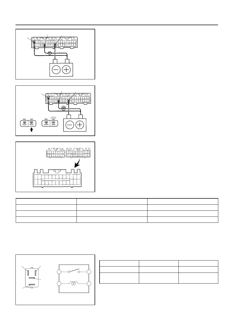
INSPECT DEFOGGER SWITCH OPERATION
(a)
Connect the positive (+) lead from the battery to terminal
29 and negative (–) lead to terminal 30.
(b)
Connect the positive (+) lead from the battery to terminal
36 through a 1.4 W test bulb.
(c)
Turn the defogger switch ON and check that the test bulb
and indicator light turn ON, then turn OFF after approx. 15
minutes.
If operation is not as specified, proceed to inspect the A/C con-
trol assembly.
(See page
)
2.
INSPECT DEFOGGER SWITCH CIRCUIT
Disconnect the connector from the switch and inspect the con-
nector on wire harness side.
Tester connection
Condition
Specified condition
30 – Ground
Constant
Continuity
29 – Ground
Ignition switch position ACC or LOCK
No voltage
29 – Ground
Ignition switch position ON
Battery positive voltage
If the circuit is not as specified, inspect the circuits connected
to other parts.
3.
INSPECT DEFOGGER RELAY CONTINUITY
Condition
Tester connection
Specified condition
Constant
1 – 2
Continuity
Apply B+ between
terminals 1 and 2.
3 – 5
Continuity
If continuity is not as specified, replace the relay.
4.
INSPECT DEFOGGER RELAY CIRCUIT
(See page
)