Lexus ES300 (1997 year). Manual - part 124
 

  Index      Lexus     Lexus ES300 - service repair manual 1997 year


Search            


Content   ..  122  123  124  125   ..


Lexus ES300 (1997 year). Manual - part 124


N21312

10

9

8

7

1

N21313

1

2

3

4

5

6

7

8

9

10

11

12

Z13911

Below 40

°

C

(104

°

F)

2

1

BE–102

BODY ELECTRICAL

COMBINATION METER

1486

1997 LEXUS ES300   (RM511U)

(f)

Connect the negative (–) lead from the battery to terminal
8.

(g)

Check that the buzzer stops sounding.

HINT:
Check the buzzer within a period of 4 to 8 seconds.
If operation is not as specified, replace the relay.

29.

Seat belt warning :
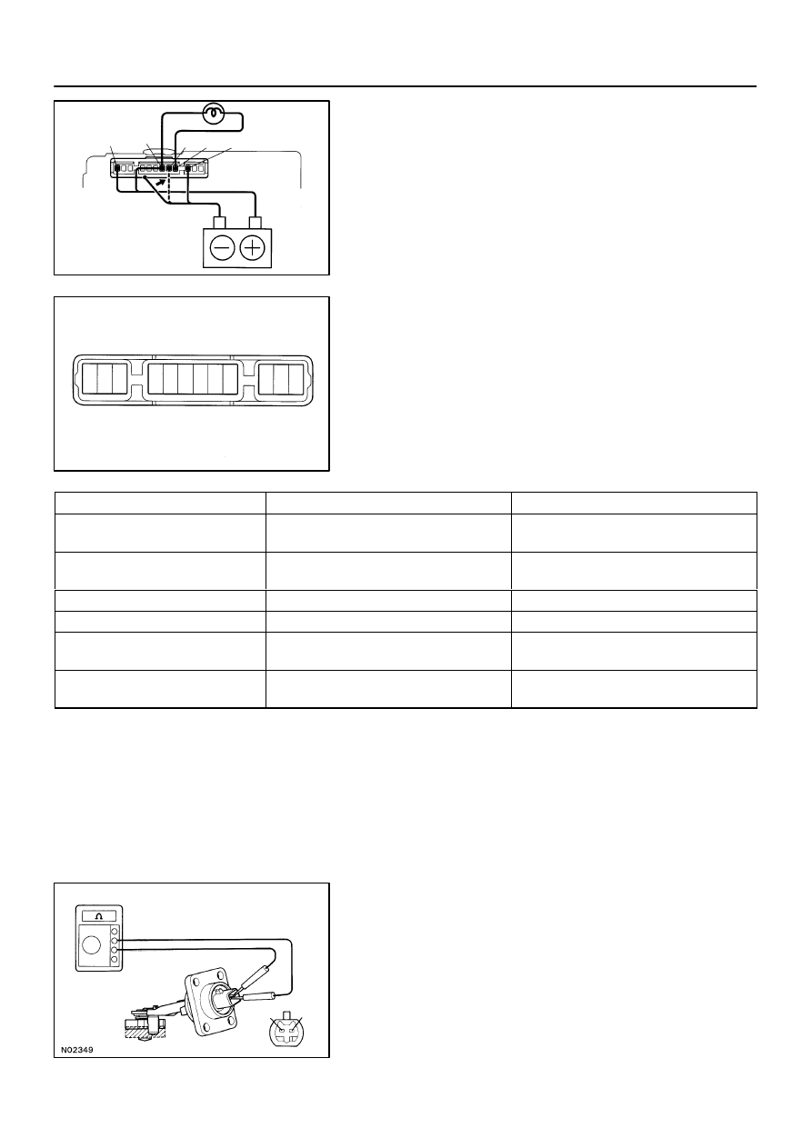
INSPECT INTEGRATION RELAY CIRCUIT

Remove the relay from the junction block No.1 and inspect the
connectors on the junction block side.

Tester  connection

Condition

Specified  condition

8 – Ground

Driver’s buckle switch OFF

(Seat best unfastened)

No continuity

8 – Ground

Driver’s buckle switch ON

(Seat best fastened)

Continuity

10 – Ground

Constant

Continuity

1 – Ground

Constant

Battery positive voltage

7 – Ground

9 – Ground

Ignition switch position OFF or ACC

No voltage

7 – Ground

9 – Ground

Ignition switch position ON

Battery positive voltage

If the circuit is as specified, try to replace the relay with a new
one.
If the circuit is not as specified, inspect the circuits connected
to other parts.

30.

INSPECT ENGINE OIL LEVEL WARNING SWITCH
CONTINUITY

(a)

Check that continuity exists between terminal with the
switch in each position.

(b)

Heat the switch to above 60

°

C (140

°

F) in an oil bath.

Z13912

Above 60

°

C

(140

°

F)

2

OFF

1

ON

Z05733

Wire Harness Side

1 2

ls–2–1–D

I03031

Ignition
Switch

Battery

Warning Light

1 2

Z09972

(a)

(b)

A

B

C

A

C

B

BODY ELECTRICAL

COMBINATION METER

BE–103

1487

1997 LEXUS ES300   (RM511U)

(c)

Check that continuity exists between terminals with the
switch ON (float up).

(d)

Check that no continuity exists between terminals with the
switch OFF (float down).

If operation is not as specified, replace the switch.

31.

INSPECT ENGINE OIL LEVEL WARNING SWITCH CIR-
CUIT

Disconnect the switch connector and inspect the connector on
wire harness side.

Tester  connection

Condition

Specified  condition

2 – Ground

Constant

Continuity

If continuity is not as specified, inspect the wire harness or
ground point.

32.

INSPECT ENGINE OIL LEVEL WARNING LIGHT

(a)

Disconnect the connector from the switch.

(b)

Turn the IG switch ON, the warning light lights up.

(c)

The warning light lights up after 40 sec. from the engine
has started.

If the warning light does not light up, inspect bulb or wire har-
ness.
33.

INSPECT LIGHT CONTROL RHEOSTAT
(See page 

BE–43

)

34.

INSPECT BULB CHECK RELAY OPERATION

(a)

Connect the positive (+) lead from the battery to terminal
C through a 1.4–W test bulb and the negative (–) lead to
terminal B, check that the test bulb does not light up.

(b)

Connect the positive (+) lead from the battery to terminal
A and check that the test bulb lights up.

If operation is not as specified, replace the relay.

BE05J–01

BE–104

BODY ELECTRICAL

COMBINATION METER

1488

1997 LEXUS ES300   (RM511U)

REASSEMBLY

Reassembly is in the reverse of the disassembly(See page 

BE–90

).

Z19374

A/C Control Panel
Assembly


 A/C Control Panel


 A/C Amplifier

Ignition Switch

Instrument Panel Junction Block


 DEF Fuse


 HEATER Fuse


 MIRROR HEATER Fuse


 Defogger Relay

RH Mirror


 Mirror Defogger

Defogger Wire

LH Mirror


 Mirror Defogger

BE05K–04

BODY ELECTRICAL

DEFOGGER SYSTEM

BE–105

1489

1997 LEXUS ES300   (RM511U)

DEFOGGER SYSTEM

LOCATION


Content   ..  122  123  124  125   ..