Lexus GS300/400 (2000 year). Manual - part 69
BE0N6–04
I05587
2
5
I05580
2
5
Z08688
2
1
3
4 5
7
6
8
Wire Harness Side
–
BODY ELECTRICAL
ANTENNA
BE–225
2526
INSPECTION
1.
Auto Antenna Models:
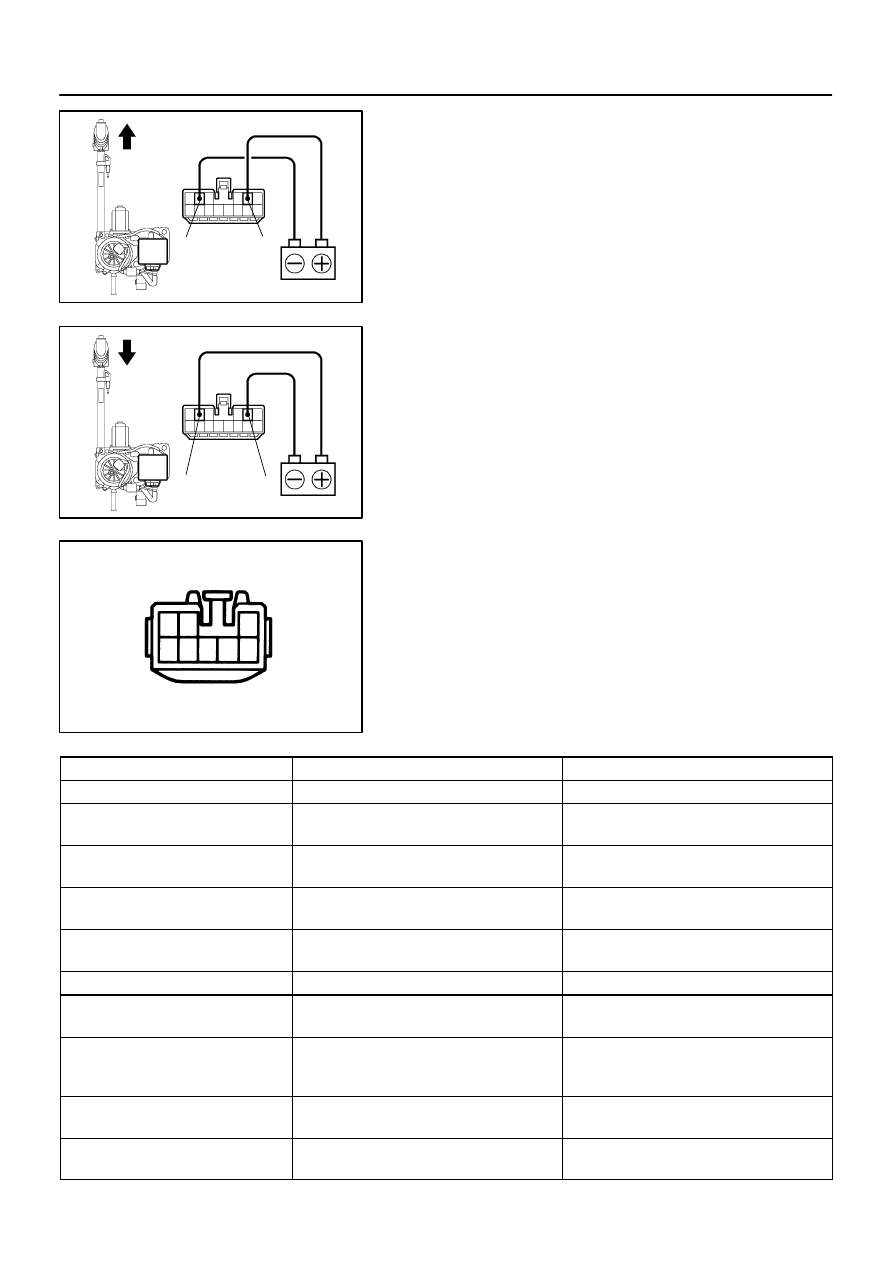
INSPECT ANTENNA MOTOR
(a)
Connect the positive (+) lead from the battery to terminal
2 and the negative (–) lead to terminal 5.
(b)
Check that the motor turns (moves upward).
NOTICE:
These tests must be done quickly (within 3 – 5 seconds) to
prevent the coil from burning out.
(c)
Then, reverse the polarity, check that the motor turns the
opposite way (moves downward).
NOTICE:
These tests must be done quickly (within 3 – 5 seconds) to
prevent the coil from burning out.
2.
Auto Antenna Models:
INSPECT ANTENNA MOTOR CONTROL RELAY CIR-
CUIT
Disconnect the connector from the relay and inspect the con-
nector on wire harness side, as shown in the chart below.
Tester connection
Condition
Specified condition
7 – Ground
Constant
Continuity
1 – Ground
Ignition switch ACC or ON,
and radio switch ON and Others
No voltage
1 – Ground
Ignition switch ACC or ON,
and radio switch ON and AM
Battery positive voltage
2 – Ground
Ignition switch ACC or ON,
and radio or tape or CD switch OFF
No voltage
2 – Ground
Ignition switch ACC or ON,
and radio or tape or CD switch ON
Battery positive voltage
3 – Ground
Constant
Battery positive voltage
4 – Ground
Ignition switch ACC or ON,
and radio switch ON and Others
No voltage
4 – Ground
Ignition switch ACC or ON,
and radio switch ON and
AM or FM (87.9 – 96.0 MHz)
Battery positive voltage
5 – Ground
Ignition switch ACC or ON,
and radio switch OFF
No voltage
5 – Ground
Ignition switch ACC or ON,
and radio switch ON
Battery positive voltage