Land Rover V8 engine 4.0, 4.6 litre. Manual - part 10


  Index      Land Rover     Land Rover V8 ENGINE 4.0, 4.6 LITRE - service manual 1997 year


Search            


Content   ..  8  9  10  11   ..


Land Rover V8 engine 4.0, 4.6 litre. Manual - part 10


ENGINE

22

OVERHAUL

Oil pump - inspection

1. Thoroughly clean oil pump drive gear, cover

plate, rotors and housing. Remove all traces of
Loctite from cover plate securing screws;
ensure tapped holes in timing cover are clean
and free from oil.

2. Check mating surfaces of cover plate, rotors

and housing for scoring.

3. Assemble rotors and oil pump drive gear in

housing ensuring that reference marks are
aligned.

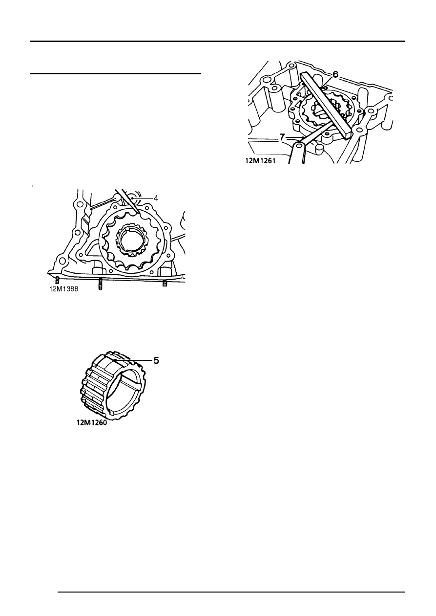
4. Using feeler gauges, check clearance between

teeth of inner and outer rotors:
Maximum clearance = 0.25 mm (0.01 in)

5. Remove oil pump drive gear, check depth of

any wear steps on gear teeth:
Wear step maximum depth = 0.15 in (0.006 in)

6. Place a straight edge across housing.
7. Using feeler gauges, check clearance between

straight edge and rotors:
Maximum clearance = 0.1 mm (0.004 in).

ENGINE

OVERHAUL

23

Oil pressure relief valve - inspection

1. Clean relief valve components and piston bore

in timing cover.

2. Check piston and bore for scoring and that

piston slides freely in bore with no perceptible
side movement.

3. Check relief valve spring for damage and

distortion; check spring free length:
Spring free length = 60.0 mm (2.4 in).

Oil pump - refit

1. Lubricate rotors, oil pump drive gear, cover

plate and housing with engine oil.

2. Assemble rotors and drive gear in housing

ensuring that reference marks are aligned.

3. Position cover plate to housing.
4. Apply Loctite 222 to threads of cover plate

screws and bolt.

5. Fit cover plate screws and bolt and tighten to:-

Screws - 4 Nm (3 lbf.ft)
Bolt - 8 Nm (6 lbf.ft)

6. Fit timing cover.

ENGINE

24

OVERHAUL

Oil pressure relief valve - refit

1. Lubricate new ’O’ ring with engine oil and fit to

relief valve plug.

2. Lubricate relief valve spring, piston and piston

bore with engine oil.

3. Assemble piston to relief valve spring, insert

piston and spring into piston bore.

4. Fit relief valve plug, depress plug and fit circlip.
5. Ensure circlip is fully seated in groove.

CAMSHAFT AND TAPPETS

Camshaft end-float - check

1. Remove rocker shaft assemblies.
2. Remove pushrods and store in their fitted

order.

3. Remove timing chain and gears.

4. Temporarily fit camshaft gear bolt.
5. Attach a suitable DTI to front of cylinder block

with stylus of gauge contacting end of
camshaft.

6. Push camshaft rearwards and zero gauge.
7. Using camshaft gear bolt, pull camshaft

forwards and note end-float reading on gauge.
End-float = 0.05 to 0.35 mm (0.002 to 0.014 in)

8. If end-float is incorrect, fit a new thrust plate

and re-check. If end-float is still incorrect, a
new camshaft must be fitted.

ENGINE

OVERHAUL

25

Camshaft and tappets - remove

1. Remove tappets and retain with their

respective pushrods.

2. When tappets prove difficult to remove due to

damaged camshaft contact area, proceed as
follows. Lift tappets in pairs to the point where
damaged face is about to enter tappet bore
and fit rubber bands to retain tappets. Repeat
until all tappets are retained clear of camshaft
lobes. The tappets can then be withdrawn out
the bottom of their bores when the sump and
camshaft are removed.

3. Remove 2 bolts securing camshaft thrust plate

to cylinder block, remove plate.

4. Withdraw camshaft, taking care not to damage

bearings in cylinder block.

NOTE: Camshafts fitted to 4.0 litre engines
are colour coded ORANGE whilst those
fitted to 4.6 litre engines are colour coded

RED.


Content   ..  8  9  10  11   ..