Land Rover Engine 1.8 Litre K Series. Manual - part 17


  Index      Land Rover     Land Rover Engine 1.8 Litre K Series - service manual 2000 year


Search            


Content   ..  15  16  17  18   ..


Land Rover Engine 1.8 Litre K Series. Manual - part 17


ENGINE

54

OVERHAUL

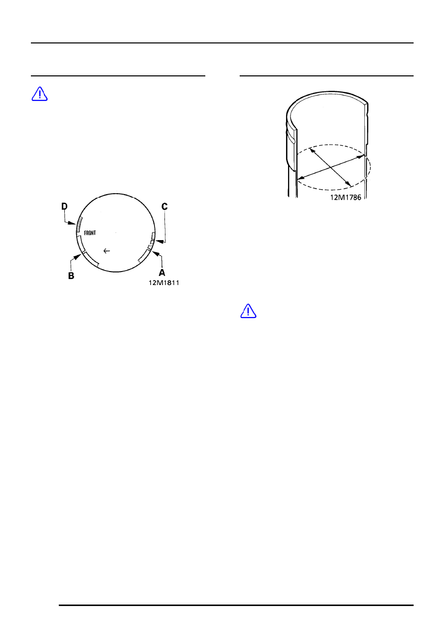
Piston rings - refit

CAUTION: Ensure that piston rings are
fitted to piston for the cylinder bore in
which they were checked.

1. Fit oil control spring.
2. With ’TOP’ or identification markings to top of

piston, use an expander to fit piston rings in
sequence; oil control, 2nd and top
compression.

3. Ensure rings are free to rotate, position

compression ring gaps and at 120

°

to

each other and away from thrust side - left
hand side of piston when viewed from front.
Position oil control ring gap and spring gap D
at 30

°

on opposite side of gudgeon pin axis.

Cylinder liners - inspection

1. Measure wear and taper in two axes 65 mm

from top of cylinder liner bore.

RED grade A = 80.000 to 80.015 mm
BLUE grade B = 80.016 to 80.030 mm

Service liners are grade A and B.
Cylinder liner grade will be found marked on
outside diameter of liner.

CAUTION: Cylinder liners with excessively
glazed, worn, scratched orscored bores
must be replaced, do not attempt to hone

or remove glazing from bore.

ENGINE

OVERHAUL

55

Later engines

A/B - Cylinder liner bore/grade

V/Z - Cylinder liner step height

NOTE: Cylinder liners fitted to later
engines have their step heights graded on
production. The step heights, V or Z

together with the liner part number and colour
code are marked on the outside diameter of the
liner. If cylinder liner(s) are to be replaced, the
replacement liner(s) must have the same step
height as the original liner(s). Both step heights
are available in red and blue grades of liner.

Cylinder liners - remove

1. Remove pistons.
2. Remove cylinder liner clamps LRT-12-144.
3. 
Using assistance, position cylinder block on its

side.

CAUTION: If original cylinder liners are to
be refitted, use a felt tipped pen to make
suitable alignment marks between liner

and cylinder block. Do not etch or stamp liners.

4. Using hand pressure, push cylinder liners out

towards cylinder head face of cylinder block;
remove liners.

CAUTION: Keep cylinder liners in their
fitted order.

ENGINE

56

OVERHAUL

Cylinder liners - refit

NOTE: To enable cylinder liner retainer
clamps to be fitted when liners are
inserted in cylinder block, crankshaft and

bearing ladder must be fitted.

1. Fit crankshaft and bearing ladder.
2. Using assistance, support cylinder block on 2

wooden blocks.

3. Remove sealant from cylinder block and if

original cylinder liners are to be refitted, from
shoulder of liners.

4. Clean cylinder liners and wipe dry.

CAUTION: Ensure that if original cylinder
liners are to be refitted, reference marks
made during dismantling are not erased.

5. Apply a 2.0 mm thick continuous bead of

sealant, Part No. GGC 102 around shoulder of
cylinder liner.

CAUTION: Do not use any other type of
sealant.

6. Keeping cylinder liner ’square’ to cylinder

block, push liner fully down until shoulder of
liner seats against cylinder block. Do not drop
liners into position.

CAUTION: If original cylinder liners are to
be refitted, align reference marks made
during dismantling before liner is pushed

fully down.

7. Fit cylinder liner retainer clamps LRT-12-144.
8. 
Fit pistons.

Pistons and connecting rods - refit

1. Using assistance, support base of cylinder

block on 2 wooden blocks.

2. Ensure that cylinder liner retainer clamps

LRT-12-144 are fitted and that feet of clamps
do not protrude over cylinder liner bores.

3. Lubricate cylinder bores, pistons and rings with

engine oil, ensure ring gaps are correctly
spaced.

4. Fit selected bearing shells into big-end bearing

caps and connecting rods.

5. Fit a suitable piston ring clamp to each piston

in turn and with ’FRONT’ mark on piston to
engine front, push piston into bore until flush
with top face of cylinder liner.
Remove ring clamp.

CAUTION: If original pistons are to be
fitted, ensure that each piston is inserted
in its correct cylinder liner. Do not push

pistons below top face of cylinder liner until
big-end bearings and caps are to be fitted.

6. Fit big-end bearings.

ENGINE

DATA, TORQUE & TOOLS

1

DATA

Oil pump
Outer rotor to housing clearance

0.28 to 0.36 mm

. . . . . . . . . . . . . . . .

Inner rotor tip clearance

0.05 to 0.13 mm

. . . . . . . . . . . . . . . . . . . . . . .

Rotor end float

0.02 to 0.06 mm

. . . . . . . . . . . . . . . . . . . . . . . . . . . . . .

Relief valve spring free length

38.9 mm

. . . . . . . . . . . . . . . . . .

Cooling system
Thermostat fully open

100

°

C

. . . . . . . . . . . . . . . . . . . . . . . .

Nominal setting

85

°

to 91

°

C

. . . . . . . . . . . . . . . . . . . . . . . . . . . .

Camshafts
Camshaft end-float

0.06 to 0.19 mm

. . . . . . . . . . . . . . . . . . . . . . . . . .

Service limit

0.3 mm

. . . . . . . . . . . . . . . . . . . . . . . . . . . . . . .

Camshaft bearing clearance

0.060 to 0.094 mm

. . . . . . . . . . . . . . . . . . .

Service limit

0.15 mm

. . . . . . . . . . . . . . . . . . . . . . . . . . . . . . .

Tappets
Tappet outside diameter

32.959 to 32.975 mm.

. . . . . . . . . . . . . . . . . . . . . .

Cylinder head
Cylinder head maximum warp

0.05 mm

. . . . . . . . . . . . . . . . . .

Cylinder head height:

New

118.95 to 119.05 mm.

. . . . . . . . . . . . . . . . . . . . . . . . . . . . . . . . . . . . .

Reface limit

0.20 mm

. . . . . . . . . . . . . . . . . . . . . . . . . . . . . . .

Valve springs
Free length

50.0 mm

. . . . . . . . . . . . . . . . . . . . . . . . . . . . . . . .

Fitted length

37.0 mm

. . . . . . . . . . . . . . . . . . . . . . . . . . . . . . . .

Load - valve closed

250

±

12 N

. . . . . . . . . . . . . . . . . . . . . . . . . .

Load - valve open

450

±

18 N

. . . . . . . . . . . . . . . . . . . . . . . . . . .

Valves
Valve stem diameter:

Inlet

5.952 to 5.967 mm

. . . . . . . . . . . . . . . . . . . . . . . . . . . . . . . . . . . . .

Exhaust

5.947 to 5.962 mm

. . . . . . . . . . . . . . . . . . . . . . . . . . . . . . . . . .

Valve guides:

Inside diameter

6.000 to 6.025 mm

. . . . . . . . . . . . . . . . . . . . . . . . . . . .

Valve stem to guide clearance:
Inlet

0.033 to 0.063 mm

. . . . . . . . . . . . . . . . . . . . . . . . . . . . . . . . . . . . . .

Service limit

0.07 mm

. . . . . . . . . . . . . . . . . . . . . . . . . . . . . . .

Exhaust

0.038 to 0.078 mm

. . . . . . . . . . . . . . . . . . . . . . . . . . . . . . . . . . .

Service limit

0.11 mm

. . . . . . . . . . . . . . . . . . . . . . . . . . . . . . .

Valve stem fitted height:
New

38.93 to 39.84 mm

. . . . . . . . . . . . . . . . . . . . . . . . . . . . . . . . . . . . . .

Service limit

40.10 mm

. . . . . . . . . . . . . . . . . . . . . . . . . . . . . . . .

Valve guides
Fitted height

6.0 mm

. . . . . . . . . . . . . . . . . . . . . . . . . . . . . . . .


Content   ..  15  16  17  18   ..