Range Rover Classic. Manual - part 120
68
AIR SUSPENSION
8
REPAIR
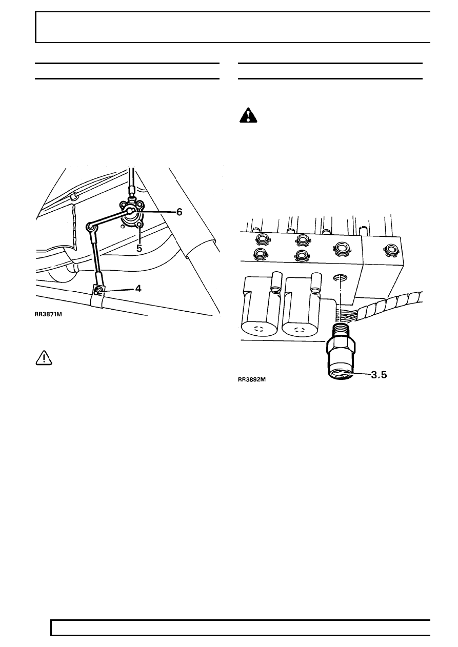
HEIGHT SENSOR
Service repair no - 60.36.01 - Front
Service repair no - 64.36.01 - Rear
Remove
1. Disconnect battery negative lead.
2. Remove wheel.
3. Disconnect height sensor multiplug.
4. Remove height sensor lower link fixing.
CAUTION: Back height sensors have
longer lower link than the front sensors.
5. Remove height sensor fixings.
6. Remove height sensor.
Refit
7. Reverse removal instructions.
8. Recalibrate system.
See Adjustment, System
Calibration - Height Sensor Datum
9. Attain standard ride height.
PRESSURE RELIEF VALVE
Service repair no - 60.50.31
WARNING: Air suspension is pressurised
up to 10 bar. Dirt or grease must not enter
the system. Wear hand, ear and eye safety
standard protection when servicing system.
Remove
1. Remove valve block.
See Valve Block
2. Clean around pressure relief valve with a stiff
brush and soapy water.
3. Remove pressure relief valve.
Refit
4. Coat threads of pressure relief valve with Loctite
572.
5. Fit valve. Tighten to
12 Nm.
6. Reverse removal procedure.