Range Rover Classic. Manual - part 113
REAR SUSPENSION
1
REPAIR
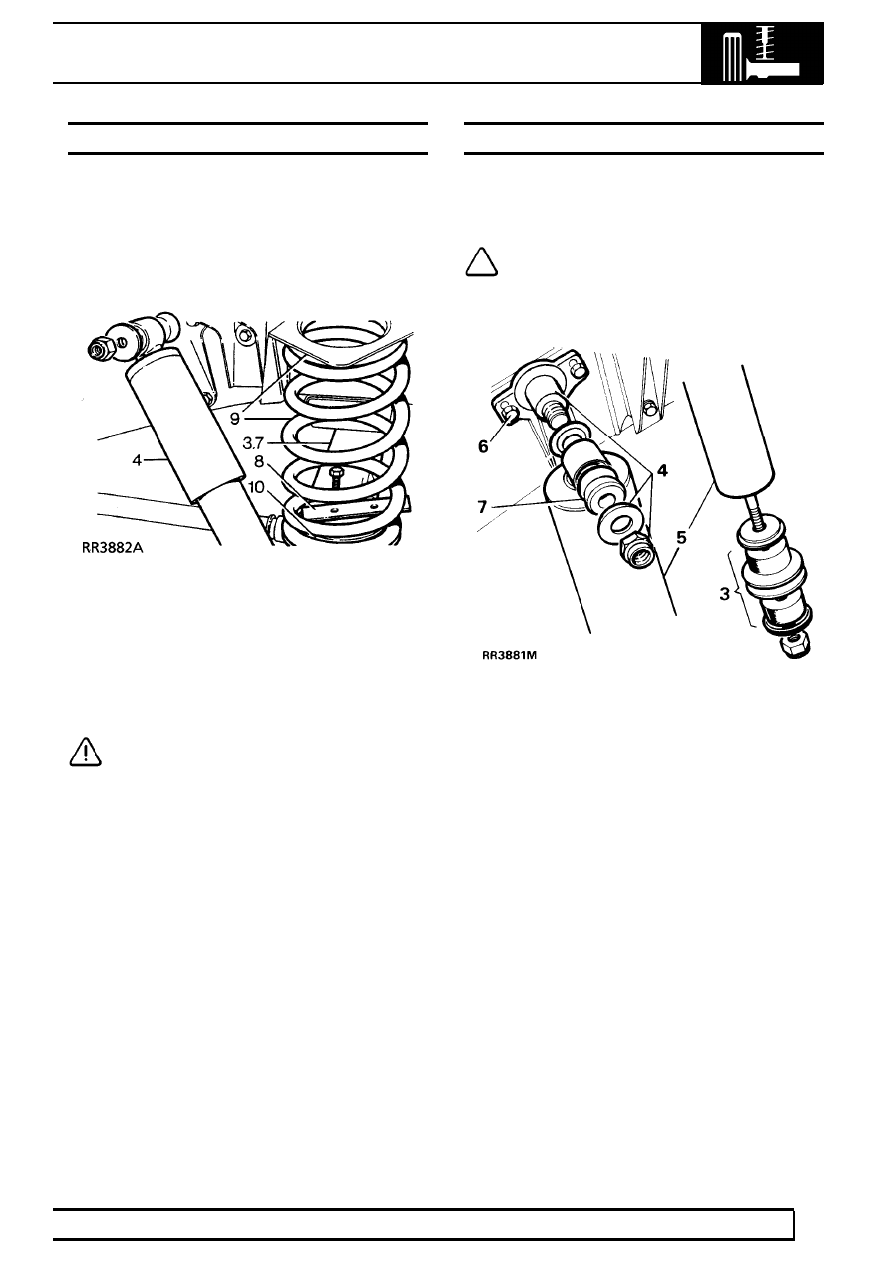
REAR ROAD SPRING
Service repair no - 64.20.01
Remove
1. Loosen rear road wheel retaining nuts.
2. Support chassis on stands and remove wheels.
3. Support rear axle weight with jack.
4. Disconnect shock absorbers at one end.
5. Position coil spring compressor correctly on road
spring.
6. Compress spring evenly to facilitate removal.
7. Lower axle to free road spring from upper seat.
CAUTION: Avoid lowering axle further than
rear brake flexible hose will allow.
8. Remove spring retainer plate.
9. Withdraw road spring and spring isolator.
10. Lift off spring.
Refit
11. Reverse removal procedure.
REAR SHOCK ABSORBER
Service repair no - 64.30.02
Remove
NOTE: Air suspension vehicles:
See AIR
SUSPENSION, Repair, Rear Damper
1. Loosen road wheel retaining nuts.
2. Support chassis on stands. Remove road wheel
and support ear axle weight with jack.
3. Remove fixings and withdraw shock absorber
from axle bracket.
4. Remove upper fixings.
5. Withdraw shock absorber.
6. If required remove mounting bracket.
7. If required remove mounting rubbers.
Refit
8. Reverse removal procedure.