Range Rover Classic. Manual - part 88


  Index      Land Rover     Range Rover Classic - service manual 1995 year


Search            


Content   ..  86  87  88  89   ..


Range Rover Classic. Manual - part 88


51

REAR AXLE AND FINAL DRIVE

10

OVERHAUL

Refit

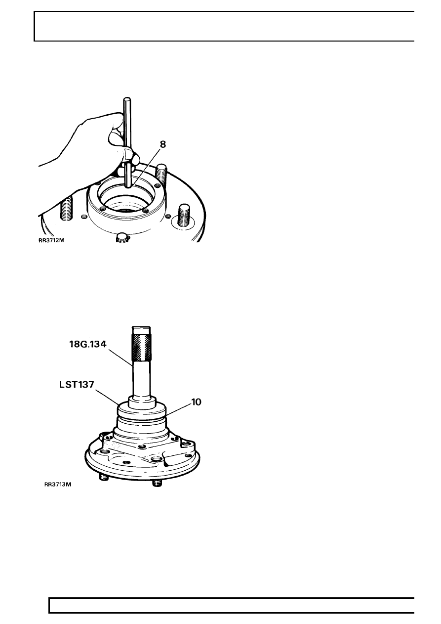
8. Clean hub and fit inner and outer bearing tracks.

9. Pack hub inner bearing with grease and fit to

hub.

10. With lip side leading fit a new seal flush with rear

face of hub. Using service tool LRT-54-003 seal
replacer and drift. Apply grease between seal
lips.

11. Assemble brake disc to the hub, line up

reassembly marks. Applying Loctite 270, fit and
tighten retaining bolts to

73 Nm.

12. If necessary, where applicable, renew sensor

ring studs applying Loctite 270 to threads. Fit
sensor ring using new nyloc nuts. Tighten to

9

Nm. Ensuring it is correctly fitted to avoid tooth
run out.

13. Pack hub outer bearing with grease and fit to

hub.

14. Fit rear hub assembly.

See Repair, Rear Hub

Assembly

REAR AXLE AND FINAL DRIVE

11

OVERHAUL

REAR STUB AXLE

Service repair no - 64.15.22.

STUB AXLE COMPONENTS

1. Rear axle shaft.
2. Stub axle to axle casing bolt.
3. Mudshield.
4. Stub axle.
5. Stub axle joint washer.
6. Axle case.
7. Sensor ABS.

Overhaul

1. Remove hub assembly.

See Repair, Rear Hub

Assembly

2. Remove six bolts from stub axle to axle casing.
3. Remove mudshield.
4. Remove stub axle and joint washer.
5. Remove rear axle shaft from axle casing.

Renew rear stub axle oil seal

6. Remove and discard oil seal. Lubricate seal and

lip with EP90 oil. Using special tool LST 138 fit
new oil seal lipside trailing so that seal is flush
with rear face of stub axle.

Refit

7. Fit new joint washer, stub axle and mudshield

with bolts. Tighten to

65 Nm.

8. Fit rear axle shaft avoid damaging stub axle

seal.

9. Refit rear hub assembly.

See Repair, Rear

Hub Assembly

REAR AXLE AND FINAL DRIVE

1

SPECIFICATIONS, TORQUE

AXLE DIFFERENTIAL DATA

Pinion bearing pre-load:

(new bearings)

3 Nm

........................................................

(bearings bedded in)

1,5 Nm

...............................................

Crown wheel run-out

0,10 mm

........................................................

Crown wheel/pinion backlash

0,10 to 0,17 mm

...........................................

REAR HUB

Rear hub end float

0,010 mm

............................................................

TORQUE VALUES

NOTE: Torque wrenches should be regularly checked for accuracy to ensure that all fixings are
tightened to the correct torque.

Nm

REAR AXLE
Pinion housing to axle case

41

.......................................................................

Crown wheel to differential case

58

................................................................

Differential bearing cap to pinion housing

90

..................................................

Differential drive flange to drive shaft

47

.........................................................

Bevel pinion nut

129

........................................................................................

Lower link to axle

176

......................................................................................

Pivot bracket ball joint to axle

176

...................................................................

REAR HUB ABS VEHICLES
Hub driving member to hub

65 *

.......................................................................

Brake disc to hub

73 *

......................................................................................

Stub axle rear to axle case

65

........................................................................

Brake caliper to axle case

82

..........................................................................

Disc shield to axle case

11

.............................................................................

Sensor ring to brake disc ABS

9

....................................................................

* Apply loctite 270 prior to assembly.

51

REAR AXLE AND FINAL DRIVE

2

SPECIFICATIONS, TORQUE

Torque values below cover all screws and bolts used, unless specified otherwise.

METRIC

Nm

M5

6

......................................................................................................

M6

9

......................................................................................................

M8

25

.....................................................................................................

M10

45

...................................................................................................

M12

90

...................................................................................................

M14

105

..................................................................................................

M16

180

..................................................................................................

UNC / UNF

1/4

9

......................................................................................................

5/16

24

...................................................................................................

3/8

39

.....................................................................................................

7/16

78

...................................................................................................

1/2

90

.....................................................................................................

5/8

136

....................................................................................................


Content   ..  86  87  88  89   ..