Range Rover Classic. Manual - part 70


  Index      Land Rover     Range Rover Classic - service manual 1995 year


Search            


Content   ..  68  69  70  71   ..


Range Rover Classic. Manual - part 70


BORG WARNER

19

OVERHAUL

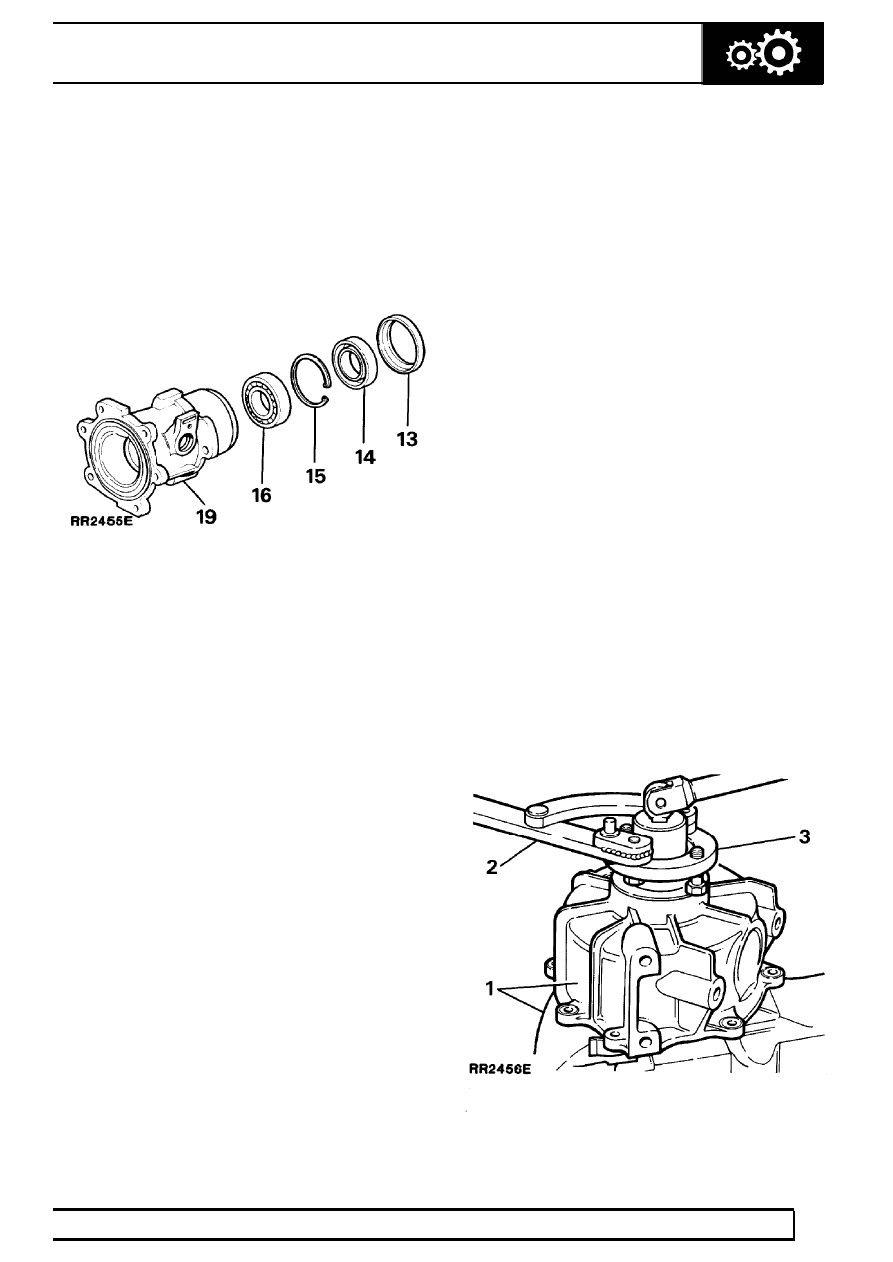
Rear output housing (continued)

13. Lever off the dust shield.
14. Prise the oil seal from the housing and discard

the seal.

15. Remove the circlip retaining the bearing.
16. Drive or press the bearing from the housing.

Discard the bearing.

17. Remove any previous sealant from the housing

joint face.

18. Thoroughly clean all components with a suitable

solvent.

19. Examine the housing for damage and wear.

Renew as necessary.

Rear output housing - Assemble

20. Drive or press a new bearing into the housing

until the bearing contacts the shoulder.

21. Fit the circlip.
22. Lubricate a new oil seal. Using oil seal replacer

18G1422 fit the seal, lip side leading until it
contacts the circlip.

23. Fit the dust shield.
24. Place the ball bearing in the indent on the output

shaft, fit the speedometer drive gear to the shaft,
secure together with the circlip.

25. Press or drive the output shaft into the housing

until the shoulder of the shaft contacts the
bearing.

26. Lubricate the oil seal bearing surface of the drive

flange and fit the flange followed by a new
rubber seal. Fit the steel washer and secure the
flange to the shaft using a new nut. Tighten to
the specified torque.

27. Lubricate a new speedometer sleeve oil seal,

press the seal into the top of the sleeve.

28. Fit a new ’O’ ring to the outside of the sleeve,

push the driven gear spindle into the sleeve.

29. Lubricate the ’O’ ring and push the sleeve and

gear assembly into the housing. It may be
necessary to rotate the output shaft to ensure
that the driven gear engages with the drive gear
on the shaft.

30. Apply Dow Corning 732 or a suitable equivalent

silicone sealant to the rear output housing joint
face on the main casing. Evenly spread the
sealant on the face to ensure a good seal.

31. Fit the housing to the main casing and secure

with the six bolts tightened to the specified
torque.

Front output housing
- Dismantle and Inspection

Service tools:
18G1422 - Oil seal replacer.
18G1205 - Adjustable flange holding wrench

1. Support the viscous unit and front output

housing in a vice fitted with soft jaws gripping on
the two flats of the viscous unit.

2. Using service tool 18G1205 to restrain the drive

flange, release and remove the nyloc nut and
plain washer securing the drive flange to the
output shaft, withdraw the rubber seal. Discard
the nut and seal.

3. Remove the drive flange from the viscous unit.

Examine the flange for damage or wear
particularly the seal running surface, if the
surface is corroded or a groove has been worn
by the previous seal discard the flange.

41

TRANSFER GEARBOX

20

OVERHAUL

4. If necessary the oil catcher can be carefully

pressed from the drive flange, if either a new oil
catcher or bolts are being fitted.

5. Carefully tap the viscous unit out of the housing.

If the original unit is being refitted wipe clean
with a clean cloth.

NOTE: The viscous unit is a sealed
assembly and cannot be further
dismantled, a new unit should be fitted if

the unit is damaged or if the torque to turn is out
of limits.

6. Prise the oil seal out from the front output

housing and discard.

7. Remove the circlip retaining the bearing.
8. Drive or press the bearing from the housing and

discard.

9. Clean the housing with a suitable solvent.

10. Remove any previous sealant from the joint face

of the housing.

11. Examine the housing for damage and wear,

renew the housing if necessary.

Front output housing - Assemble

12. Drive or press a new bearing into the housing
13. Fit the circlip to retain the bearing.
14. Lubricate a new oil seal. Using oil seal replacing

tool 18G1422 fit the seal, lip side of the seal
leading until it contacts the circlip.

15. Carefully tap the original or new viscous unit into

the housing until contact is made with the face of
the bearing.

16. Lubricate the lips of the seal and fit the flange

followed by a new rubber seal; fit the steel
washer and secure the flange with a new nut.
Tighten to the specified torque.

17. Apply Dow Corning 732 or a suitable equivalent

silicone sealant to the output housing joint face
of the main casing. Evenly spread the sealant on
the face to ensure a good seal.

18. Fit the housing to the main casing and secure in

position with the eight bolts tightened evenly to
the specified torque.

19. Refit the gearbox to the vehicle.

BORG WARNER

1

SPECIFICATIONS, TORQUE

TORQUE VALUES

NOTE: Torque wrenches should be regularly checked for accuracy to ensure that all fixings are
tightened to the correct torque.

Nm

Brake drum back plate to rear output housing

73

...........................................

Brake drum to drive flange

25

.........................................................................

Centre differential (front to rear)

60

.................................................................

Drive flanges to transfer gearbox

224

..............................................................

Driven gear to centre differential

50

................................................................

Front cover to rear cover - main case

40

........................................................

Front output housing to main case

33

.............................................................

Gearbox mounting brackets to chassis

45

......................................................

Mounting bracket to gearbox

102

....................................................................

Neutral warning switch

47

...............................................................................

Oil drain plug

25

..............................................................................................

Oil filler/level plug

25

.......................................................................................

Oil pump fixings

7

..........................................................................................

Propeller shafts to drive flanges

46

.................................................................

Rear output housing to main case

40

.............................................................

Selector lever shaft

8

.....................................................................................

Selector fork operating arm

8

.........................................................................

Torque values below are for all screws and bolts used except for those that are specified otherwise.

METRIC

Nm

M5

6

......................................................................................................

M6

9

......................................................................................................

M8

25

.....................................................................................................

M10

45

...................................................................................................

M12

90

...................................................................................................

M14

105

..................................................................................................

M16

180

..................................................................................................

UNC / UNF

1/4

9

......................................................................................................

5/16

24

...................................................................................................

3/8

39

.....................................................................................................

7/16

78

...................................................................................................

1/2

90

.....................................................................................................

5/8

136

....................................................................................................

BORG WARNER

1

SERVICE TOOLS

ADAPTER PLATE TRANSFER BOX

Adaptor plate for removing Borg Warner transfer
gearbox. This can be manufactured locally to drawing
shown.

Material: Steel BS 1449 Grade 4 or 14.
Drill holes marked * to fit hoist used.


Content   ..  68  69  70  71   ..